Indoor Unit SiBE121135_A
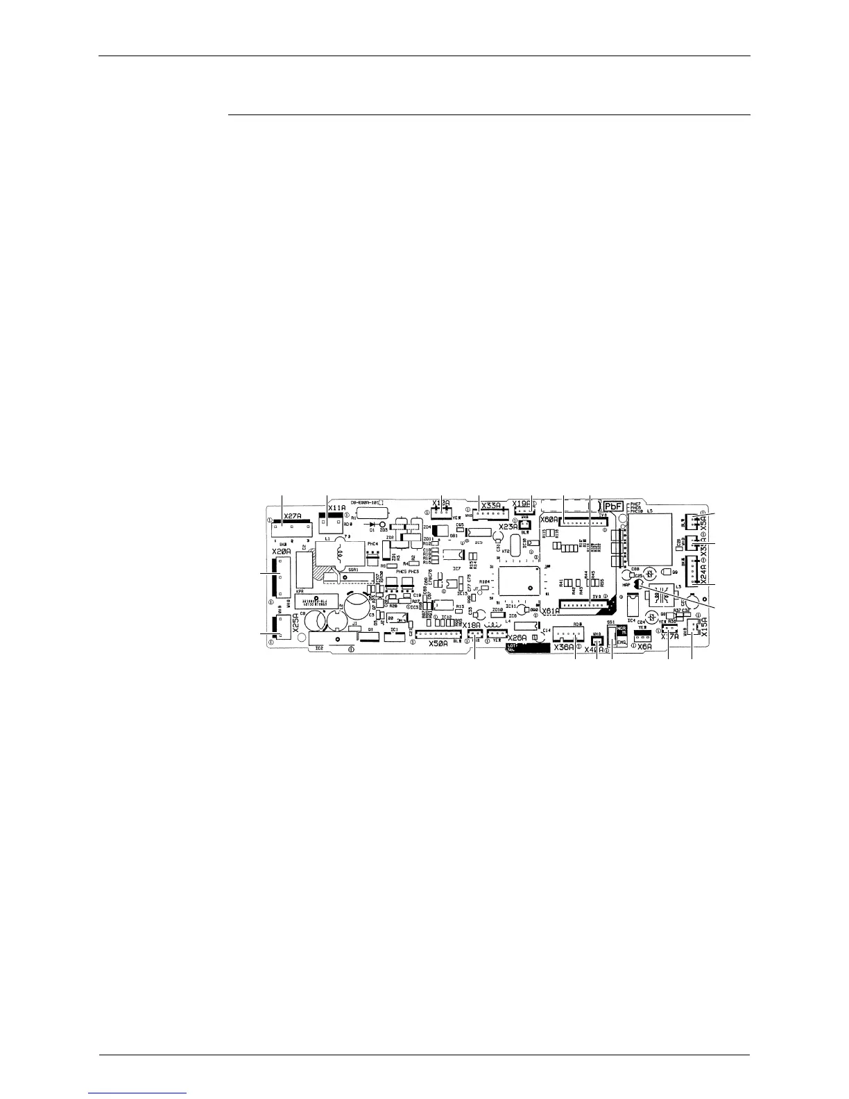
65 Printed Circuit Board Connector Wiring Diagram
2.10 FFQ25/35/50/60B9V1B
Control PCB
1) X5A Connector for terminal board (for wired remote controller)
2) X10A, X11A Connector for transformer
3) X15A Connector for float switch
4) X17A, X18A Connector for indoor heat exchanger thermistor
5) X19A Connector for room temperature thermistor
6) X20A Connector for fan motor
7) X24A Connector for signal receiver PCB
(when the wireless remote controller is used)
8) X25A Connector for drain pump motor
9) X27A Connector for terminal board (for inter-unit wiring)
10) X33A Connector for wiring adaptor PCB (option)
11) X35A Connector for group control adaptor (option)
12) X36A Connector for swing motor
13) X40A Connector for ON/OFF input from outside (option)
14) X60A, X61A Connector for interface adaptor (option)
15) HAP LED for service monitor (green)
16) SS1 Selector switch for emergency
X27A X11A X33AX10A X19A X60A X61A
X5A
X35A
X24A
HAP
X15AX17ASS1X40AX36AX18A
X25A
X20A
2P197080-6

 Loading...