SiBE121135_A Function of RA Indoor Unit
Function and Control 80
1.5 Fan Speed Control for Indoor Unit
Outline Phase control and fan speed control contains 9 steps: LLL, LL, SL, L, ML, M, MH, H, and HH.
The airflow rate can be automatically controlled depending on the difference between the room
thermistor temperature and the target temperature. This is done through phase control and Hall
IC control.
For more information about Hall IC, refer to the troubleshooting for fan motor on page 173, 176.
Automatic Fan
Speed Control
In automatic fan speed operation, the step “SL” is not available.
= The airflow rate is automatically controlled within this range when the [FAN] setting
button is set to automatic
.
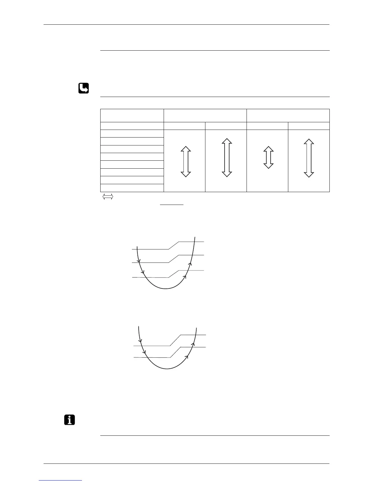
<Cooling>
The following drawing explains the principle of fan speed control for cooling.
Wall Mounted Type, Floor Standing Type
*The upper limit is M tap in 30 minutes from the operation start.
Floor / Ceiling Suspended Dual Type, Duct Connected Type
<Heating>
In heating operation, the fan speed is regulated according to the indoor heat exchanger
temperature and the difference between the room thermistor temperature and the target
temperature.
Note: 1. During POWERFUL operation, the fan rotates at H tap + 40 ~ 90 rpm.
2. The fan stops during defrost operation.
COMFORT
AIRFLOW
Operation
Wall Mounted Type
The fan speed is controlled automatically.
The latest command has the priority between POWERFUL and COMFORT AIRFLOW.
Wall Mounted Type
Floor Standing Type
Floor / Ceiling Suspended Dual Type
Duct Connected Type
Step Cooling Heating Cooling Heating
LLL
LL
L
ML
M
MH
H
HH (POWERFUL)
(R11681)
(R6834)
(R6833)
(R6834)
(R12317)
Fan speed
+2.5°C
+1.5°C
+0.5°C
MH*
M
ML
L
+3°C
+2°C
+1°C
Room thermistor temperature – target temperature
Room thermistor temperature – target temperature
+1.5˚C
+0.5˚C
+2˚C
+1˚C
M
ML
L
Fan speed
(R12390)

 Loading...