8. Login to the switch again , this time the password is Scaleio123
9. Type enable and click enter.
10. Type configure terminal (or config) to enter global configuration mode.
11. Type interface management 0 to enter interface configuration mode for the
virtual interface which accesses management port 1 on the currently active
supervisor.
12. Type ip address, followed by the desired address, to assign a virtual IP
address for access to the active management port.
Example, this command assigns the IP address 10.0.2.5 to management port 0:
l
switch(config-if-Ma0)#ip address 10.0.2.5/24
13. Type end twice at the interface configuration and global configuration prompts
to return to Privileged EXEC mode.
14. Type write (or copy running-config startup-config) to save the new
configuration to the startup-config file.
15. Disconnect the service laptop from the console port IOIO.
16. Repeat this procedure if required to configure additional management switches.
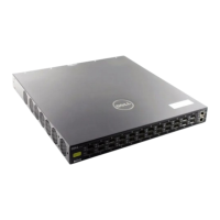
Install the data switch in the cabinet
There are two cabinet rails (left and right). Each cabinet rail consists of the part that
is installed in the cabinet (slide rail) and the part that is mounted on the side of the
management switch (inner rail).
When the data switch is installed in the cabinet, the rear panel will be facing the front
of the cabinet.
Procedure
1. Separate the inner rails from the slide rails.
2. Install the slide rails in the cabinet with the hardware provided.
3. Place one of the inner rails on the chassis with attachment pins protruding
through key-openings.
4. Slide the inner rail toward the front flange until the bracket clip locks with an
audible click.
5. Repeat the previous two steps to install the inner rail to the other side of the
data switch.
6. Lift the data switch to the cabinet and insert the inner slides into the slide rails.
7. Slide the data switch on the rails, toward the rear posts, until flush with the rail
flanges attached to the cabinet posts.
8. Secure the data switch to the front of the cabinet with two screws (one on
each side).
9. Repeat this procedure to install an additional data switch.
10. Repeat this procedure if required to install an additional data switch.
2U4N Configuration Equipment Installation
46 VxRack Node Hardware Installation Guide
 Loading...