EasyManua.ls Logo

Dell 100 Series User Manual

Dell 100 Series
116 pages
To Next Page IconTo Next Page
To Previous Page IconTo Previous Page
Page #82 background imageLoading...
Page #82 background image
Data Switch A
Source Destination
Node8 MB1 Mezz1 Port1 Data Network Switch A Port 38
Node8 MB2 Mezz0 Port0 Data Network Switch A Port 36
Node8 MB2 Mezz1 Port1 Data Network Switch A Port 34
Node8 MB3 Mezz0 Port0 Data Network Switch A Port 10
Node8 MB3 Mezz1 Port1 Data Network Switch A Port 12
Node8 MB4 Mezz0 Port0 Data Network Switch A Port 14
Node8 MB4 Mezz1 Port1 Data Network Switch A Port 16
Management Server Port0 Data Network Switch A Port 32
Data network B nodes 1 - 3 and 9 - 11 wiring for 2U4N
configuration in a single-phase cabinet
Use Figure 37 and table that follows to connect the data network B cables for nodes 1
- 3 and 9 - 11.
Wiring Diagrams for a 2U4N Configuration in a Cabinet with Single-Phase Power Distribution
82 VxRack Node Hardware Installation Guide

Table of Contents

Question and Answer IconNeed help?

Do you have a question about the Dell 100 Series and is the answer not in the manual?
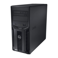
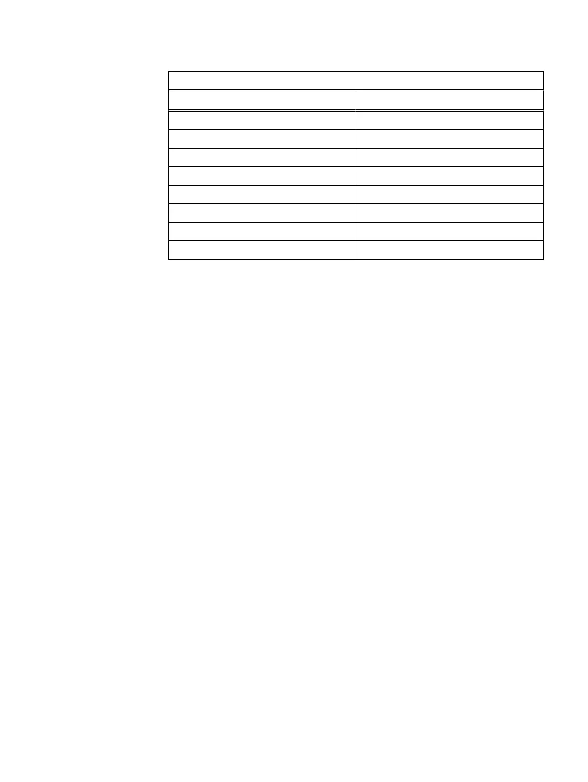
Dell 100 Series Specifications

General IconGeneral
ProcessorIntel Xeon E3-1200 series
Hard DrivesUp to 2 x 3.5" SATA HDD
StorageSATA
Expansion Slots1 x PCIe x16
NetworkingDual Gigabit Ethernet

Summary

Chapter 1: Before You Begin

Site Requirements

Outlines the essential environmental and facility prerequisites for installation.

Hardware Acclimation Times

Specifies the necessary time for hardware to acclimate to the operating environment.

Installing a 2U1N Configuration in a 40U Cabinet

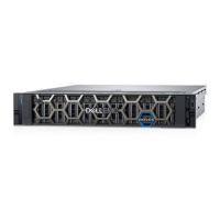
Details the procedure for physically installing a 2U1N server configuration in a 40U cabinet.

Installing a 2U4N Configuration in a 40U Cabinet

Details the procedure for physically installing a 2U4N server configuration in a 40U cabinet.

Chapter 2: 2U1N Configuration Equipment Installation

2U1N Configuration Installation Guidelines

General guidelines for installing 2U1N components, including minimum and maximum configurations.

Install the 2U1N Server in the Cabinet

Step-by-step instructions for physically installing the 2U1N server into a rack.

Chapter 3: 2U4N Configuration Equipment Installation

Install the 2U4N Server in the Cabinet

Step-by-step instructions for physically installing the 2U4N server into a rack.

Install the Management Server in the Cabinet

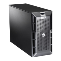
Procedure for installing the management server, including verifying mounting kit parts.

Install the Management Switch in the Cabinet

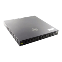
Steps to install the management switch into the server rack cabinet.

Chapter 7: Update the Install Database

Update the Install Database

Procedure for updating the system's installation database after all work is completed.

Related product manuals