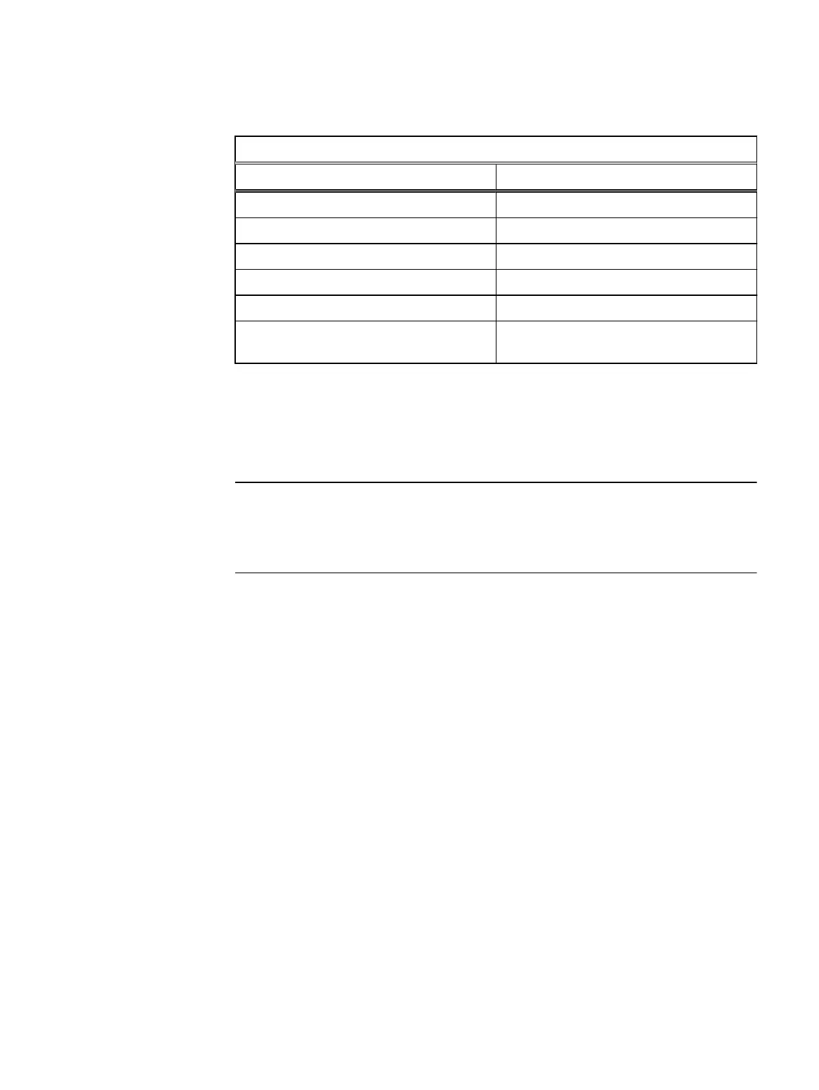
Table 9 Management network cabling (continued)
Management Switch Arista 7010
Source Destination
Node17 BMC Management Switch Port 29
Node17 NIC1 Management Switch Port 31
Data Network Switch A Mgmt Port Management Switch Port 47
Data Network Switch B Mgmt Port Management Switch Port 48
Management Server NIC1 Management Switch Port 38
Link to Core Switch or 2nd Rack Management
Switch
Management Switch Port 52
Data network A wiring for 2U1N configuration
Use the Figure 29 and Table 10 to connect the data network A cables.
Space on the page with Figure 29 does not provide enough space to illustrate cabling
of the maximum number of nodes in data network A. However, Table 10 does provide
all the source to destination cabling for the maximum network.
Wiring Diagrams for a 2U1N Configuration
60 VxRack Node Hardware Installation Guide
 Loading...