Steps
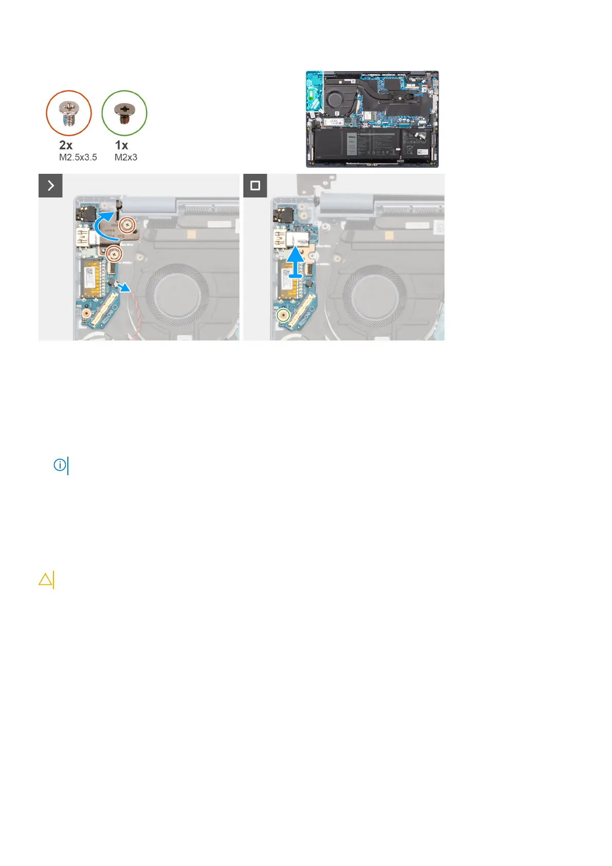
1. Remove the two screws (M2.5x3.5) that secure the left display hinge to the I/O daughter-board and the palm-rest and
keyboard assembly.
2. Using a plastic scribe, pry open the left display hinge upwards at an angle of 90 degrees.
3. Disconnect the coin-cell battery cable from the connector on the I/O daughter-board.
4. Open the latch and disconnect the fingerprint reader flexible printed circuits cable from the connector on the I/O daughter-
board.
NOTE: This step applies only to computers shipped with a power button with fingerprint reader installed.
5. Remove the screw (M2x3) that secures the I/O daughter-board to the palm-rest and keyboard assembly.
6. Carefully slide and remove the I/O daughter-board at angle, from the palm-rest and keyboard assembly, to clear the ports
from the port openings.
Installing the I/O daughter-board
CAUTION: The information in this section is intended for authorized service technicians only.
Prerequisites
If you are replacing a component, remove the existing component before performing the installation procedure.
About this task
The following images indicate the location of the I/O daughter-board and provide a visual representation of the installation
procedure.
64
Removing and installing Field Replaceable Units (FRUs)
 Loading...