Steps
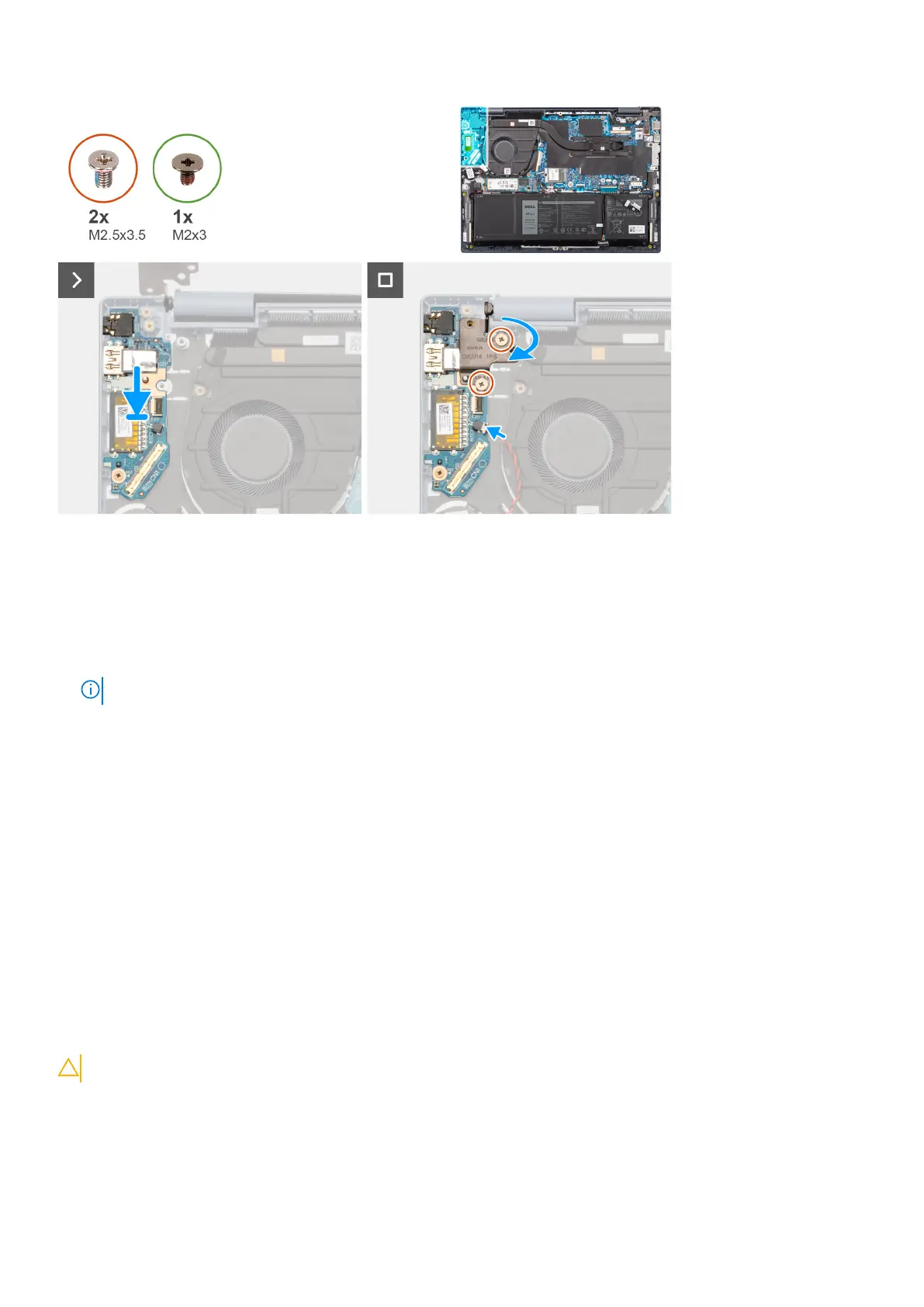
1. Align the ports on the I/O daughter-board to the port openings on the palm-rest and keyboard assembly.
2. Carefully slide and place the I/O daughter-board at an angle, on the palm-rest and keyboard assembly.
3. Align the screw hole on the I/O daughter-board to the screw hole on the palm-rest and keyboard assembly.
4. Replace the screw (M2x3) to secure the I/O daughter-board to the palm-rest and keyboard assembly.
5. Connect the fingerprint reader flexible printed circuits cable to the connector on the I/O daughter-board and close the latch.
NOTE: This step applies only to computers shipped with a power button with fingerprint reader installed.
6. Connect the coin-cell battery cable to the connector on the I/O daughter-board.
7. Close the left display hinge downwards to align the screw holes on the left display hinge to the screw holes on the I/O
daughter-board and the palm-rest and keyboard assembly.
8. Replace the two screws (M2.5x3.5) to secure the left display hinge to the I/O daughter-board and the palm-rest and
keyboard assembly.
Next steps
1. Install the I/O daughter-board cable.
2. Install the base cover.
3. Follow the procedure in After working inside your computer.
Coin-cell battery
Removing the coin-cell battery
CAUTION: The information in this section is intended for authorized service technicians only.
Prerequisites
1. Follow the procedure in Before working inside your computer.
2. Remove the base cover.
3. Remove the I/O daughter-board cable.
Removing and installing Field Replaceable Units (FRUs)
65
 Loading...