4. Remove the two screws (M2.5x3.5) that secure the right display hinge to the system board and palm-rest and keyboard
assembly.
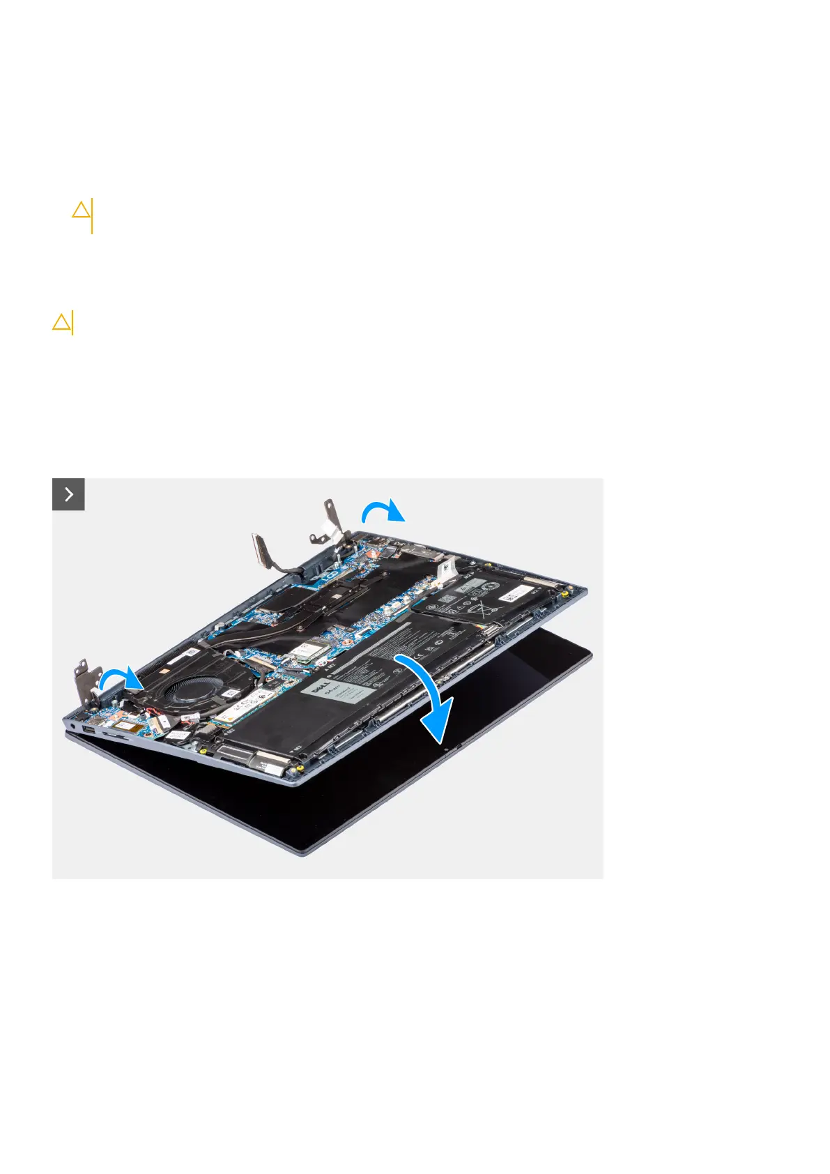
5. Using a plastic scribe, pry open the left display hinge upwards at an angle of 90 degrees.
6. Using a plastic scribe, pry open the right display hinge upwards at an angle of 90 degrees.
7. Gently lift the palm-rest and keyboard assembly at an angle and remove the palm-rest and keyboard assembly from the
display assembly.
CAUTION: To avoid damaging the display, do not slide the palm-rest and keyboard assembly over the display
assembly.
Installing the display assembly
CAUTION: The information in this section is intended for authorized service technicians only.
Prerequisites
If you are replacing a component, remove the existing component before performing the installation procedure.
About this task
The following images indicate the location of the display assembly and provide a visual representation of the installation
procedure.
74
Removing and installing Field Replaceable Units (FRUs)
 Loading...