Steps
1. Remove the two screws (M2x3) that secure the display-cable bracket to the palm-rest assembly..
2. Lift the display-cable bracket off the palm-rest assembly.
3. Remove the three screws (M2x4) that secure the Type-C bracket to the palm-rest assembly..
4. Lift the Type-C bracket off the palm-rest assembly.
5. Disconnect the fingerprint-reader cable from the system board.
6. Disconnect the eDP cable from the connector on the system board.
7. Disconnect the display cable from the connector on the system board.
8. Remove the display cable from the routing guides on the system board.
9. Open the latch and disconnect the touchpad cable from the connector on the system board.
10. Open the latch and disconnect the USH cable from the USH module.
11. Disconnect the coin-cell battery cable from the connector on the system board.
12. Disconnect the speaker cable from the connector on the system board.
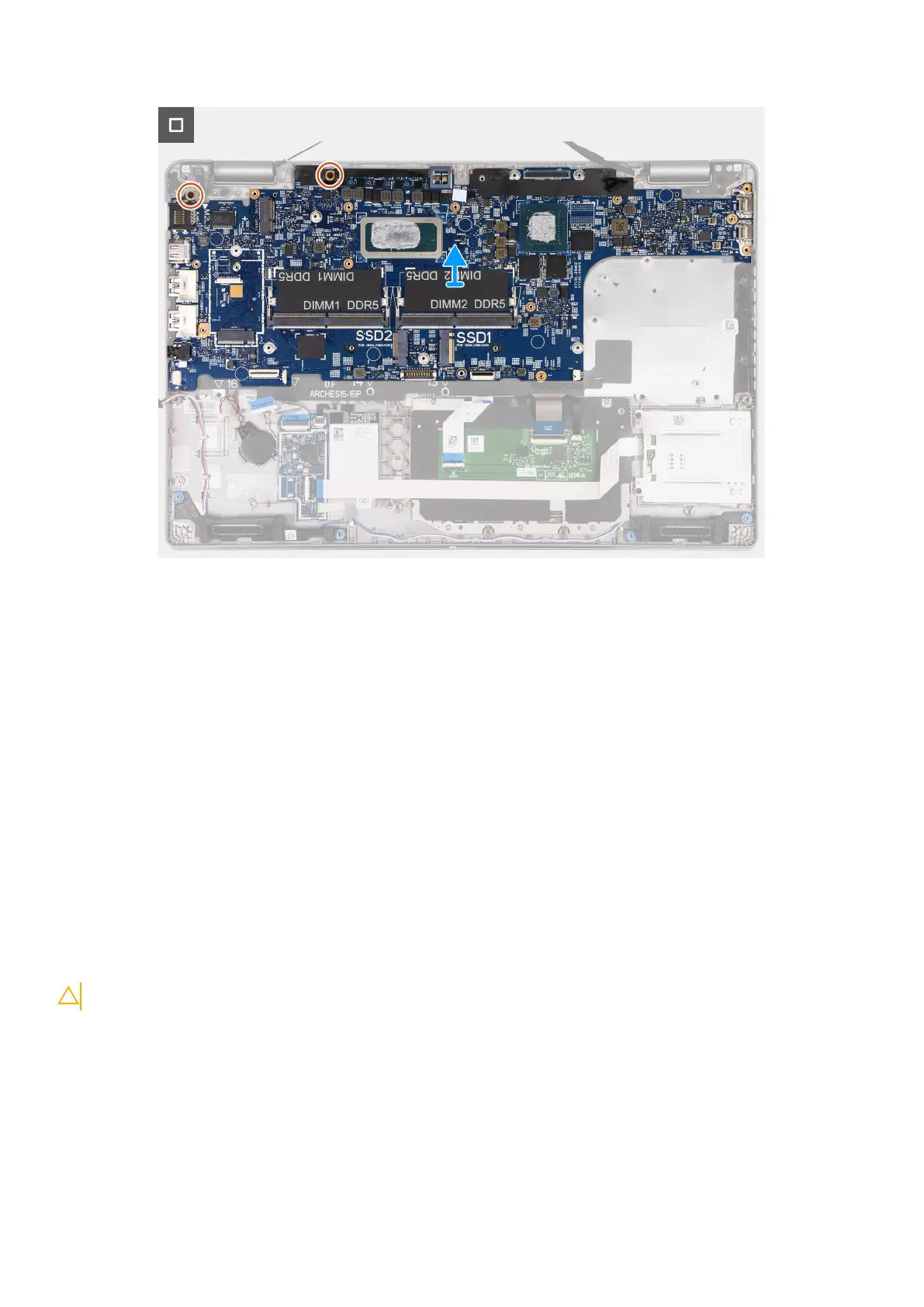
13. Remove the three screws (M2x3) that secure the system board to the palm-rest assembly.
14. Lift the system board off the palm-rest assembly.
Installing the system board
CAUTION: The information in this section is intended for authorized service technicians only.
Prerequisites
If you are replacing a component, remove the existing component before performing the installation process.
About this task
The following images indicate the system board connectors.
86
Removing and installing Field Replaceable Units (FRUs)
 Loading...