5. Remove the 4G WWAN card or 5G WWAN card, as applicable.
6. Remove the WLAN card.
7. Remove the memory modules.
8. Remove the M.2 2230 or M.2 2280 solid-state drive from Slot 1, as applicable.
9. Remove the M.2 2230 solid-state drive from Slot 2, if applicable.
10. Remove the heat sink (discrete GPU) or heat sink (integrated GPU), as applicable.
11. Remove the assembly-inner frame.
12. Remove the system board.
About this task
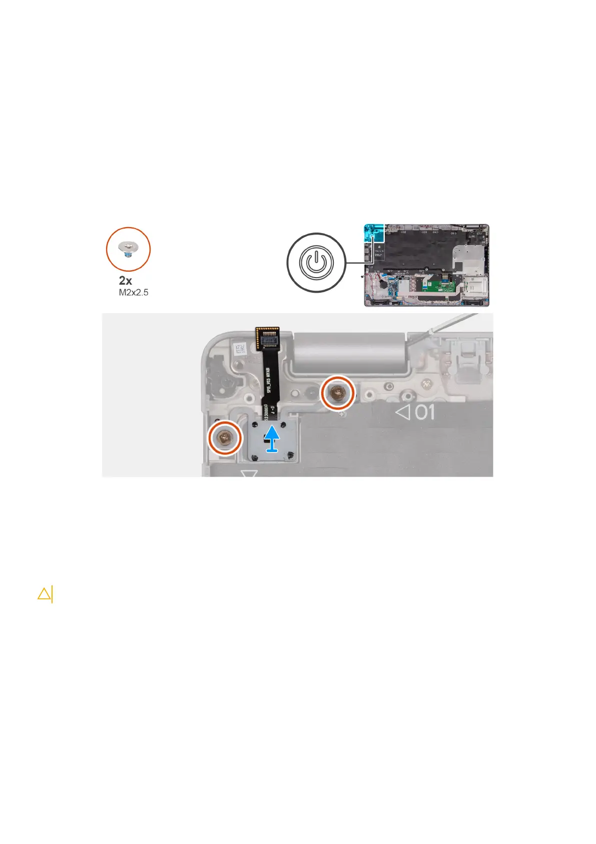
The following images indicate the location of the power button and provide a visual representation of the removal procedure.
Steps
1. Remove the two (M2x2.5) screws that secure the power button to the palm-rest assembly.
2. Lift the power button, along with the cable. off the palm-rest assembly.
Installing the power button with optional fingerprint reader
CAUTION: The information in this section is intended for authorized service technicians only.
Prerequisites
If you are replacing a component, remove the existing component before performing the installation process.
About this task
The following images indicate the location of the power board and provide a visual representation of the installation procedure.
Removing and installing Field Replaceable Units (FRUs)
93
 Loading...