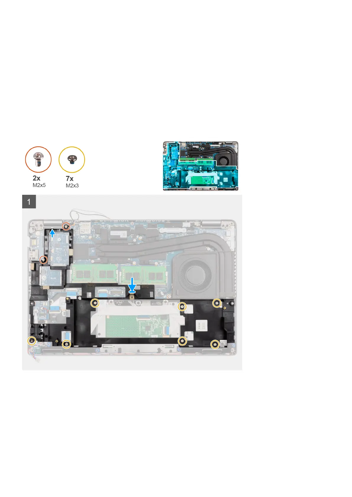
4. Remove the seven screws (M2x3) that secure the assembly inner frame to the system board and the palm-rest assembly .
5. Lift the assembly inner frame off the system board and the palm-rest assembly.
Installing the assembly inner frame
Prerequisites
If you are replacing a component, remove the existing component before performing the installation procedure.
About this task
The following image indicates the location of the assembly inner frame and provides a visual representation of the installation
procedure.
Removing and installing components 39

 Loading...