Steps
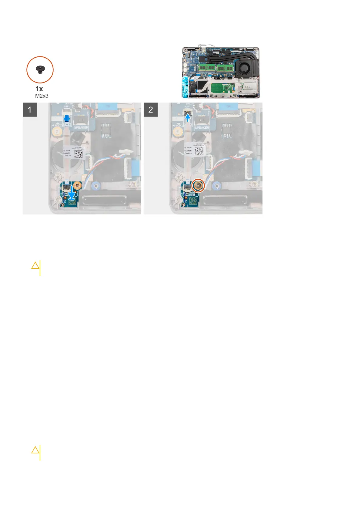
1. Align the screw hole on the LED board with the screw hole on the palm-rest assembly.
2. Replace the single screw (M2x3) to secure the LED board to the palm-rest assembly.
3. Route the LED-board cable and connect the cable to the connector on the system board.
CAUTION:
Do not route the LED-board cable under the coin-cell battery. Incorrect routing of the LED-board
cable may damage the LED board, LED-board cable, and system board.
Next steps
1. Install the assembly inner frame.
2. Install the battery.
3. Install the WWAN card.
4. Install the WLAN card.
5. Install the 2280 solid-state drive or 2230 solid-state drive.
6. Install the base cover.
7. Install the microSD card.
8. Install the SIM card.
9. Exit Service Mode.
10. Follow the procedure in After working inside your computer.
Heat sink and fan assembly
Removing the heat sink and fan assembly - UMA configuration
Prerequisites
1. Follow the procedure in Before working inside your computer.
CAUTION:
For maximum cooling of the processor, do not touch the heat transfer areas on the heat sink. The
oils in your skin can reduce the heat transfer capability of the thermal grease.
42 Removing and installing components
 Loading...