15
Installation and Operation Manual for Inverter RPI M50A_12s V1 EU EN 2017-03-09
4 Product overview
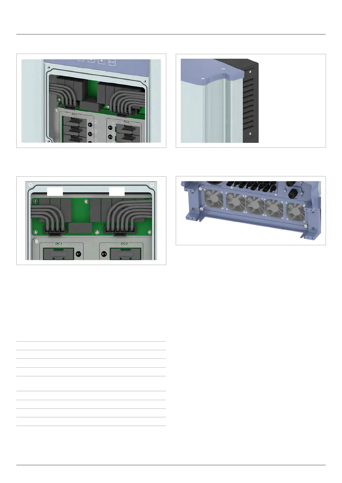
4.5 Surge protection devices
Fig. 4.6: Position of the surge protection devices on the
inverter
AC DC
Fig. 4.7: Assignment of the surge protection devices (AC and
DC)
The inverter has replaceable type 2 surge protection devices on
the AC side and the DC side. The surge protection devices pro-
tect the inverter from excessively high voltages.
The surge protection devices are located behind the fuse box
cover.
Type for the AC side
Type 2 OCM as per EN 61643-11
Nominal current I
n
10 kA (8/20)
Maximum current I
max
20 kA (8/20)
Voltage U
P
1.8 kV
Type for the DC side
Type 2 OCM as per EN 50539-11
Current I
n
20 kA (8/20)
Current I
max
40 kA (8/20)
Voltage U
P
≤3.9kV
4.6 Air inlets, air outlets and fans
Fig. 4.8: Air inlets are located at the top of the left and right
sides
Fig. 4.9: Position of the fans and air outlet on the inverter
Ambient air is sucked into the air inlets by the fans, passed
through the inverter for cooling and the heated air is then
expelled to the environment via the air outlet.
 Loading...


