53
Installation and Operation Manual for Inverter RPI M50A_12s V1 EU EN 2017-03-09
6 Installation
6.5.3 Connecting a data logger via RS485
Cable and wiring requirements
● Shielded twisted-pair cable with solid conductors (CAT 5 or
CAT 6.
● Cable diameter: 5 mm
● Wire cross-section: 1 mm
2
► Lay the cable with a suitable clearance to the AC and DC
cables to prevent interference in the data connection.
NOTICE
Unwanted currents.
Unwanted currents can flow when multiple invert-
ers are connected via RS485.
► Do not use GND and VCC.
► If the cable shield is used for providing
lightning protection then the housing of only
one inverter in the RS485 chain should be
grounded.
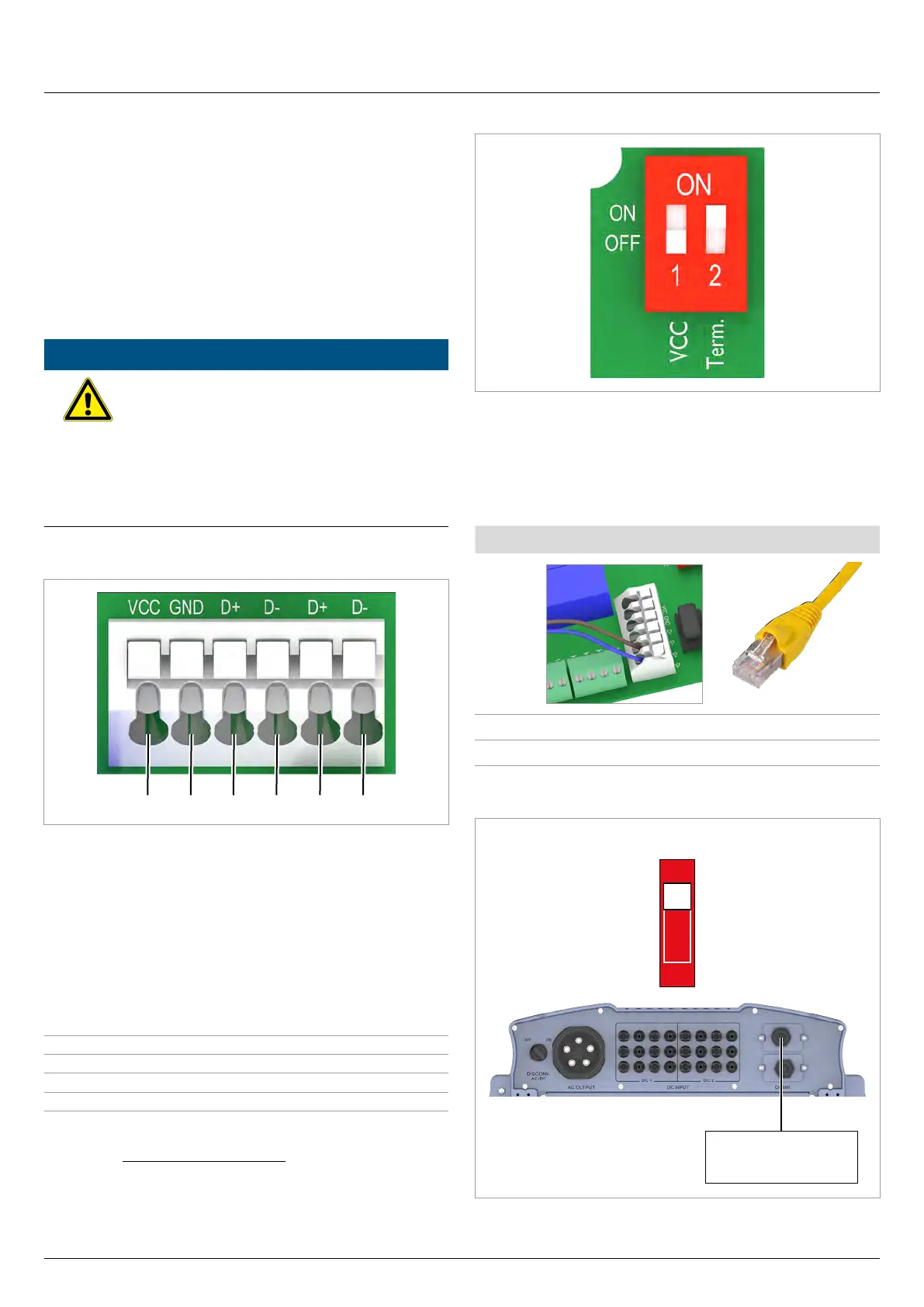
Terminal assignments of the RS485 terminal block
1 2 3 4 5 6
1 VCC (+12 V; 0.5 A)
2 GND
3 D+ (DATA+ RS485)
4 D– (DATA+ RS485)
5 D+ (DATA+ RS485)
6 D– (DATA+ RS485)
Terminal pairs 3/4 or 5/6 can be used. The second terminal pair
is only required when connecting several inverters via RS485.
Data format
Baud rate 9600, 19200, 38400; standard: 19200
Data bits 8
Stop bit 1
Parity Not applicable
The baud rate can be set on the inverter display after commis-
sioning, see “8.3.3 Baud rate”, page 80.
DIP switch for RS485 termination resistor and VCC
1 VCC (+12 V; 0.5 A)
2 RS485 termination resistor
Connection to a Delta SOLIVIA Gateway M1 G2
Individual wires are connected at the inverter and an RJ45 plug is
used at the gateway.
Inverter SOLIVIA Gateway M1 G2
DATA+ Terminal 3 or 5 Pin 7
DATA– Terminal 4 or 6 Pin 6 or 8
Wiring diagram for a single inverter
ON
1
RS485
Termination resistor = ON
Data logger
 Loading...


