Chapter 17 Safe Torque Off FunctionMS300 (High Speed Model)
17-4
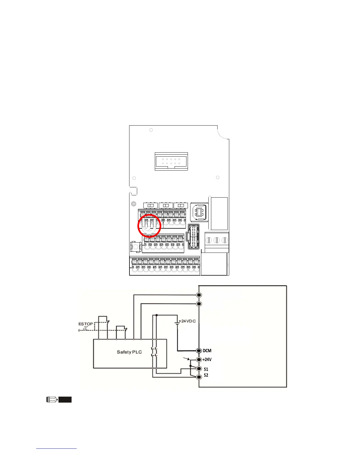
17-3 Wiring Diagram
17-3-1. Internal circuit diagram of safe control loop is shown in Figure2.
17-3-2. Terminals of the safe control loop + 24V-S1-S2 are short-circuited together with jumper
wire at the factory, as shown in Figure 2.
17-3-3. The safe control loop wiring diagram is as follows:
1.
Remove the jumper wire of +24V
-S1-S2.
2.
The wiring as shown in Figure 3 below. Normally, the switch ESTOP
contact must be
closed, ther
eby the drive can output without error displayed.
3.
In STO mode, the switch ESTOP is turned on. The drive stops outputting
and keypad
displays ST
O.
Figure 2
Figure 3
NOTE
*
1 is factory jumper wire of +24V-S1-S2. To use the Safety function, please remove this jumper wire.
Conversely, if the Safety function is disabled, then +24V-S1-S2 should be short-circuit with jumper
wire.
MO2 (Factory setting: 66)
MCM
*1
 Loading...