Chapter 7 Optional Accessories MS300 (High Speed Model)
7-20
Installation
During installation, please pass the cable through at least one zero-phase reactor.
Use a suitable cable type (insulation class and wire section) so that the cable passes easily through the
zero-phase reactor. Do not pass the grounding cable through zero-phase reactor; only pass the motor
wire through.
With longer motor cables the zero-phase reactor can effectively reduce interference at the motor
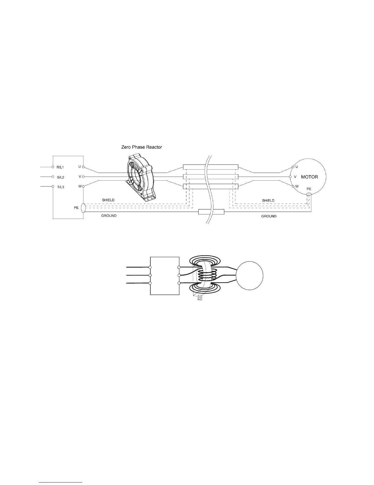
output. Install the zero-phase reactor as close to the output of the drive as possible. Figure A is the
installation diagram of a single turn zero-phase reactor. If the diameter allows several turns, the
installation of a multi-turn zero-phase reactor is as shown in Figure B. The more turns, the better the noise
suppression effect.
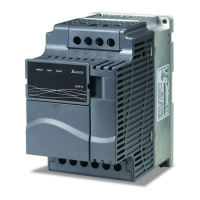
Figure A: Single turn wiring diagram of a shieling wire with a zero-phase reactor
Power
Supply
Zero Phase Reactor
MOTOR
U/T1
V/T2
W/T3
R/L1
S/L2
T/L3
Figure B: Multi-Turn Zero Phase Reactor
Installation notices
Install the zero-phase reactor at the output terminal of the frequency converter (U.V.W.).
After the zero-phase reactor is installed, the electromagnetic radiation and load stress emitted by the
wiring of the frequency converter is reduced. The number of zero-phase reactor required for the drive
depends on the length of wiring and the voltage of the drive.
The normal operating temperature of the zero-phase reactor should be lower than 85 °C (176 °F).
However, when the zero-phase reactor is saturated, its temperature may exceed 85°C (176 °F). Please
increase the number of zero-phase reactors to avoid saturation. The following are reasons that might
cause saturation of the zero-phase reactors. For example: The wiring of the drive is too long; the drive
has several sets of load; the wiring is in parallel; the drive uses high capacitance wiring. If the
temperature of the zero-phase reactor exceeds 85 °C (176 °F) during the operation of the drive, the
number of the zero-phase reactor should be increased.
 Loading...