12
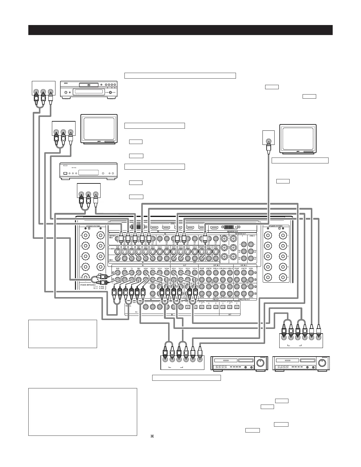
Connecting Video Components
•To connect the video signal, connect using a 75 Ω/ohms video signal cord. Using an improper cable can result in a drop in picture quality.
• When making connections, also refer to the operating instructions of the other components.
• The AVC-A1XVA is equipped with a function for up and down converting video signals. (See page 17)
The signal connected to the video signal terminal is output to the S-Video and component video monitor out terminals.
But the REC OUT terminals have no conversion function, so when recording connect the appropriate video terminals.
R OUT
VIDEO
OUT
L
AUDIO
R OUT
VIDEO
OUT
L
AUDIO
R OUT IN
AUDIO
VIDEO
OUT IN
LRL
R OUT IN
AUDIO
VIDEO
OUT IN
LRL
R OUT
VIDEO
OUT
L
AUDIO
IN
VIDEO
R
L
R
L
R
L
R
L
R
L
R
L
R
L
R
L
R
L
R
L
R
L
R
L
R
L
R
L
B
TV
DVD player or video disc player (VDP), etc.
Monitor
Connecting a TV tuner
TV
• Connect the TV’s tuner’s video output jack (VIDEO OUTPUT) to the
(yellow) TV IN jack using a 75 Ω/ohms video coaxial pin plug
cord.
• Connect the TV’s tuner’s audio output jacks (AUDIO OUTPUT) to the
TV IN jacks using pin plug cords.
AUDIO
VIDEO
C
onnecting a DVD player or a video disc player (VDP)
DVD
• Connect the video disc player’s video output jack (VIDEO OUTPUT) to the (yellow) DVD IN jack using a
75 Ω/ohms video coaxial pin plug cord.
• Connect the video disc player’s analog audio output jacks (ANALOG AUDIO OUTPUT) to the DVD IN
jacks using pin plug cords.
• VDP can be connected to the VDP jacks in the same way.
AUDIO
VIDEO
MONITOR OUT
• Connect the TV’s video input
jack (VIDEO INPUT) to the
MONITOR OUT jack
using a 75 Ω/ohms video
coaxial pin plug cord.
VIDEO
Note on connecting the digital
input jacks
• Only audio signals are input to
the digital input jacks. For details,
see page 11.
Video deck 2Video deck 1
• There are four sets of video deck (VCR) jacks, so four video decks can be connected for
simultaneous recording or video copying.
Video input/output connections:
• Connect the video deck’s video output jack (VIDEO OUT) to the (yellow) VCR-1 IN jack,
and the video deck’s video input jack (VIDEO IN) to the (yellow) VCR-1 OUT jack using
75 Ω/ohms video coaxial pin plug cords.
Connecting the audio output jacks
• Connect the video deck’s audio output jacks (AUDIO OUT) to the VCR-1 IN jacks, and the
video deck’s audio input jacks (AUDIO IN) to the VCR-1 OUT jacks using pin plug cords.
Connect other video decks to the VCR-2, VCR-3 or VCR-4 jacks in the same way.
AUDIO
AUDIO
VIDEO
VIDEO
Connecting the video recorders
Connecting a monitor
Connecting a DBS tuner
DBS
• Connect the DBS tuner’s video output jack (VIDEO OUTPUT) to the
(yellow) DBS IN jack using a 75 Ω/ohms video coaxial pin
plug cord.
• Connect the DBS tuner’s audio output jacks (AUDIO OUTPUT) to the
DBS IN jacks using pin plug cords.
AUDIO
VIDEO
NOTE:
• Connecting a LD (laser disc) player with a Dolby
Digital RF Output.
The AVC-A1XVA does not have a DD RF demodulator
function. Therefore, you need to use a commercially
available outboard DD RF demodulator and connect its
digital output to one of the AVC-A1XVA available digital
inputs. Refer to the demodulator’s owner’s manual for
further information.
DBS tuner
 Loading...