Module operation Serial communications
XBee/XBee-PRO ZigBee RF Modules User Guide 26
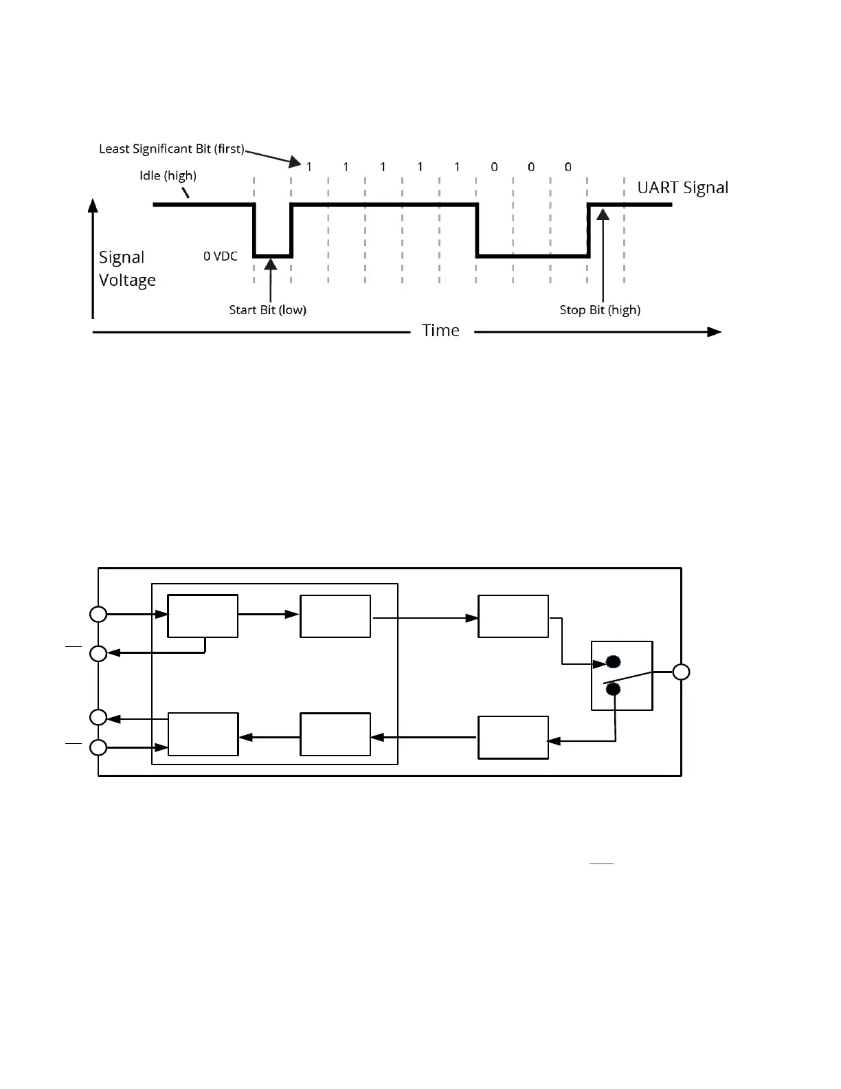
UART data packet 0x1F (decimal number “31”) as transmitted through the RF module
Example data format is 8-N-1 (bits - parity - # of stop bits)
Serial communications depend on the two UARTs (the microcontroller's and the RF module's) to be configured
with compatible settings (baud rate, parity, start bits, stop bits, data bits).
The UART baud rate, parity, and stop bits settings on the XBee module can be configured with the BD, NB, and SB
commands respectively. See Command reference tables on page 153 for details.
Serial buffers
The XBee modules maintain small buffers to collect received serial and RF data, which is illustrated in the figure
below. The serial receive buffer collects incoming serial characters and holds them until they can be processed.
The serial transmit buffer collects data that is received via the RF link that will be transmitted out the UART.
Internal data flow diagram
Serial receive buffer
When serial data enters the RF module through the DIN Pin (pin 3), the data is stored in the serial receive buffer
until it can be processed. Under certain conditions, the module may not be able to process data in the serial
receive buffer immediately. If large amounts of serial data are sent to the module, CTS
flow control may be
required to avoid overflowing the serial receive buffer.
Cases in which the serial receive buffer may become full and possibly overflow:
1 If the module is receiving a continuous stream of RF data, the data in the serial receive buffer will not be
transmitted until the module is no longer receiving RF data.

 Loading...


