Maintenance 7. Joint #3
11
2 LS20-B Rev.4
Apply the proper tension to the Z belt, and
secure the Joint #3 motor unit.
Z belt tension
: 93N (9.5 ± 0.75 kgf)
Axial tension (if being pulled): 186N
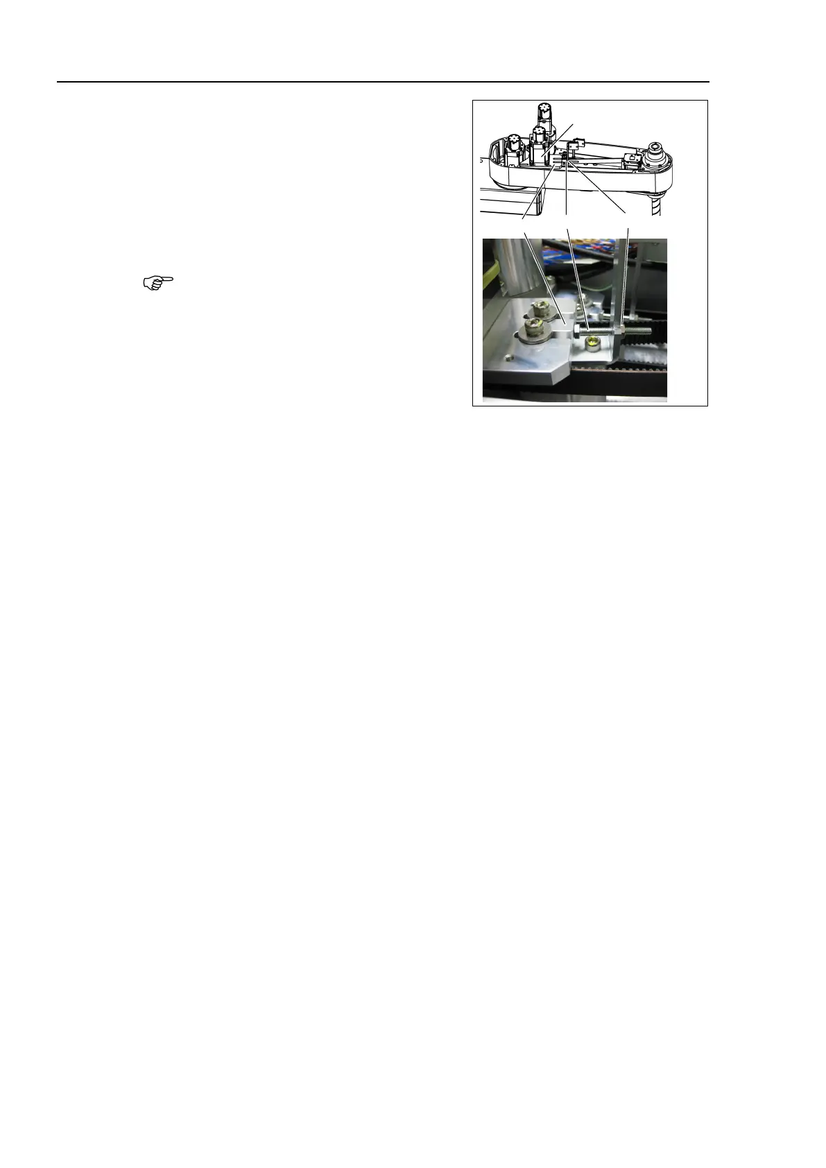
To apply tension to the Joint #3 motor unit,
use the bolt at the front.
M4 Nut
Joint #3
Motor Unit
Plate
M4 Bolt
(4)-1 Loosen the nut and turn the bolt. Push in the Joint #3 motor unit slowly.
(4)-2 After fixing the Joint #3 motor unit, turn the bolt to leave from the plate.
(4)-3 Check the tension using the sonic tension meter.
For details, refer to Maintenance 7.4 Checking the Timing Belt Tension.
(4)-4 Repeat the steps (4)-1 through (4)-3 until you get appropriate tension.
(4)-5 After the adjustment, put the bolt back to its original position and fix it with
the nut.
Mount the User Plate and the Duct Plate.
For details, refer to Maintenance 3. Covers.
Connect the following connectors.
Connectors: X231, X43
Install the clip band removed in the removal step (5), bind the cables, and then fix them.
Do not allow unnecessary strain on the
cables.
Install the Arm Top Cover.
For details, refer to Maintenance: 3.1 Arm Top Cover.
Check if the Joint #3 moves in a Jog motion by operating from EPSON RC+ menu
[Tools]-[Robot Manager]-[Jog & Teach].
If the Manipulator oscillates with MOTOR ON and the following errors are detected,
Error 5041: Motor torque output failure in low power state.
Error 4241: Over speed during low power mode was detected.
or when the joint other than Joint #3
moves, the connector for other joint might be
connected to the Joint #3 motor. Check the connector connection.
Execute the calibration of Joints #3, #4.
For details, refer to Maintenance: 13. Calibration.
 Loading...


