Setup & Operation 5. Motion Range
LS20-B Rev.4 49
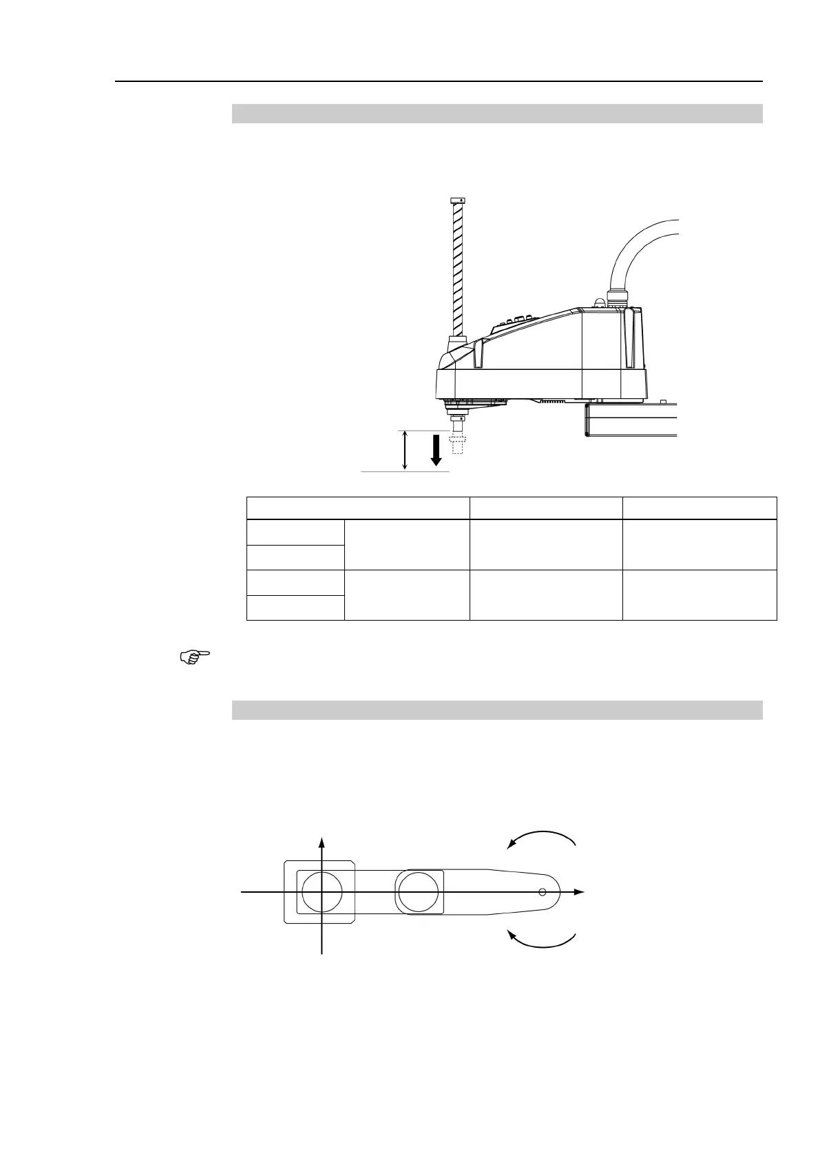
5.1.3 Max. Pulse Range of Joint #3
The 0 (zero) pulse position of Joint #3 is the position where the shaft is at its upper limit.
The pulse value is always negative because Joint #3 always moves lower than the 0 pulse
position.
Joint #3 Stroke Lower Limit Pulse
LS20-B804S
Standard-model 420 mm
−283853 pulse
LS20-BA04S
LS20-B804C
Cleanroom-model 390 mm
−263578 pulse
LS20-BA04C
For the Cleanroom-model, the motion range set with the Joint #3 mechanical stop cannot be
changed.
5.1.4 Max. Pulse Range of Joint #4
The 0 (zero) pulse position of Joint #4 is the position where the flat near the end of the shaft
faces toward the end of Arm #2. With the 0 pulse as a starting point, the counterclockwise
pulse value is defined as the positive (+) and the clockwise pulse value is defined as the
negative (-).
: +X 0 ± 344064 pulse
+Y
Clockwise (-value)
Counterclockwise (+value)
 Loading...


