Setup & Operation 5. Motion Range
L
S20-B Rev.4 53
5.2.2 Setting the Mechanical Stop of Joint #3
This method applies only to the Standard-model (LS20-B**4S) manipulator.
For the Cleanroom-model (LS20-B**4C), the motion range set with the Joint #3 mechanical
stop cannot be changed.
Turn ON the Controller and turn OFF the motors using the Motor OFF command.
Push up the shaft while pressing the brake release switch.
Do not push the shaft up to its upper limit or it will be
difficult for the arm top cover to
be removed. Push the shaft up to a position where the Joint #3 mechanical stop can
be changed.
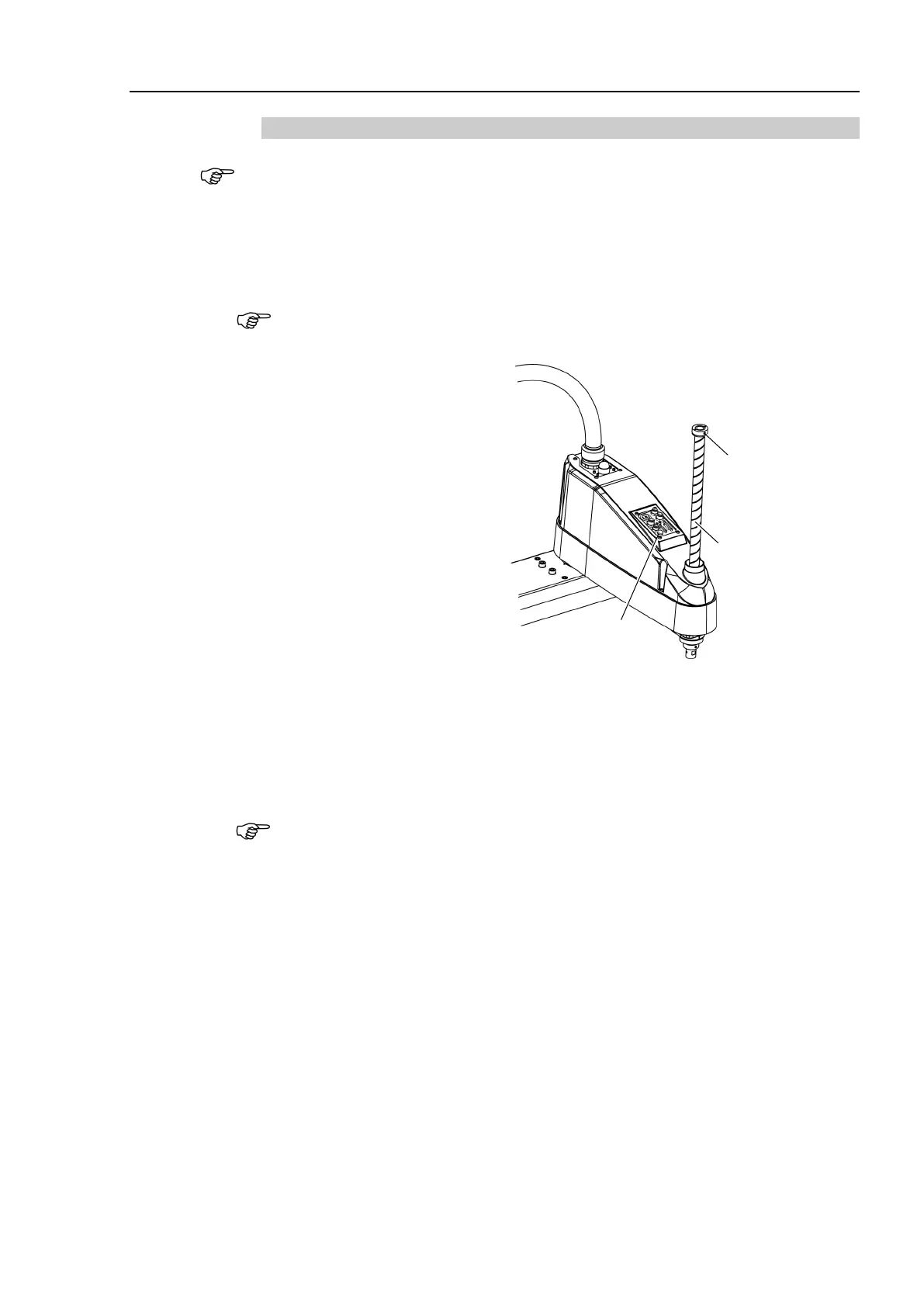
Lower limit mechanical
stop screw
Set screw: 2-M5×6
+2-M5 Bushing
Brake Release Switch
Shaft
the brake release switch, the shaft may lower or rotate due to the
f the end effector. Be sure to hold the shaft by hand while pressing the button.
Controller.
Loosen the lower limit mechanical stop screw
(set screws: 2-M5×6).
mounted on both the top and bottom of Joint #3. However, only
the position of the lower limit mechanical stop on
the top can be changed.
Do not remove the upper limit mechanical stop on the bottom because the calibration
point of Joint #3 is specified
using the stop.
 Loading...


