Setup & Operation 2. Specifications
16
LS20-B Rev.4
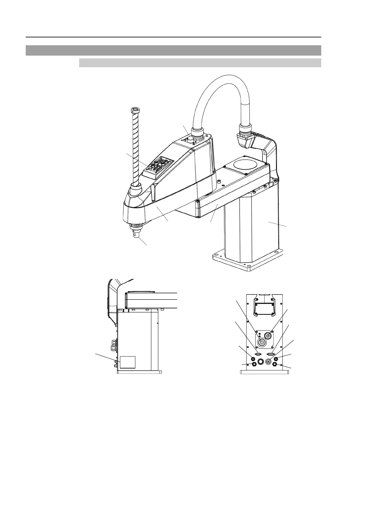
2.3 Part Names and Outer Dimensions
2.3.1 Standard-Model (LS20-B**4S)
Brake release switch
Arm #1
Arm #2
Base
Shaft
LED lamp
Signature label
(Serial No.
of Manipulator)
Power cable
Fittings for ø8 mm
pneumatic tube (No. 3)
Fittings for ø8 mm
pneumatic tube (No. 2)
User connector
(15-pin
D-sub connector)
Ethernet connector
Fittings for ø6 mm
pneumatic tube (No. 1)
Signal cable
Fittings for ø6 mm
pneumatic tube (No. 4)
User connector
(9-pin D-sub connector)
- T
he brake release switch affects both Joints #3 and #4. When the brake release switch
is pressed in emergency mode, the brakes for both Joint #3 and Joint #4 are release
d
s
imultaneously.
- While the LED lamp is on, current is being applied to the manipulator. Performing any
work with the power ON is extremely hazardous and it may result in electric shock and/or
improper function of the robot system. Make sure to turn OFF the controller power
before the maintenance work.
 Loading...


