Maintenance 7. Joint #3
LS20-B Rev.4 119
Joint #3 brake
Removal
Push down the shaft to its lower limit while pres
sing the brake release switch.
Be sure to keep enough space and prevent
the end effector hitting any
The brake release switch is applied to both Joints #3 and Joint #4.
When the brake release switch is pressed, the respective brakes of the Joint #3 and Joint
#4 are
released simultaneously.
shaft falling and rotating while the brake release switch is
because the shaft may be lowered by the weight of an end effector.
Arm Top Cover.
For details, refer to Maintenance: 3.1 Arm Top Cover.
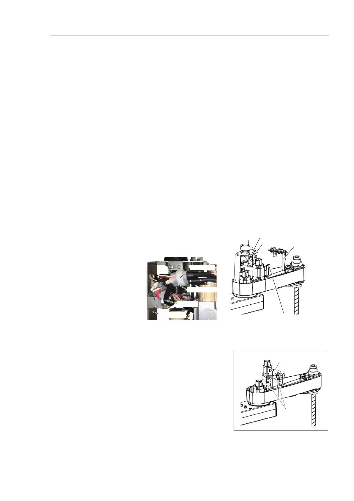
sheet bundling the motor cables.
Cut off the wire tie fixing the cable
s to the belt tensioner.
o not cut the wire tie (in the duct fittings outlet) that binds the cables to the duct
will be used again. Be careful not to lose them.
Clip Band
Wire Tie
Duct Plate
Silicon Sheet
Clip Band
Duct Plate
User Plate
Belt Tensioner
Disconnect the following connectors.
Connectors: X231, X43, BR3
fixing the Joint #3 motor
The washers for slotted holes will be used
again when installing the Z belt.
Be careful
Joint #3
Motor Unit
3-M5×20
+ washer for
slotted hole
 Loading...


