2-5
2.3 Wiring
Follow the procedure below. (In the following description, the inverter has already been installed.)
2.3.1 Removing and mounting the terminal block (TB) cover and the front cover
(1) For inverter with a capacity of 4.0 kW and Single Phase 2.2kW.
1) First loosen the front cover fixing screw, slide the cover downward holding its both sides, tilt it toward you,
and then pull it upward, as shown below.
2) While pressing the wiring guide upward, pull it out toward you.
3) After carrying out wiring (see Sections 2.3.2 through 2.3.7), put the wiring guide and the front cover back into place
in the reverse order of removal.
Figure 2.5 Removing the covers and wiring guide
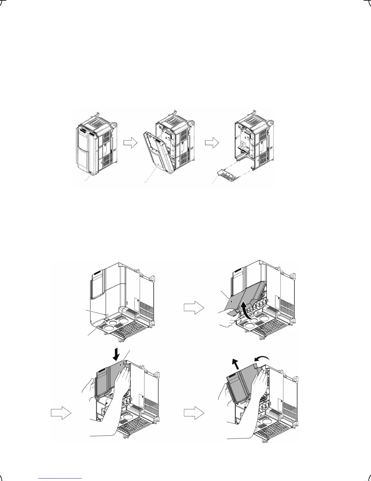
(2) For inverters with a capacity from 5.5 to 22 kW
Removing the covers
1) To remove the TB cover, loosen the fastening screw on it, hold the dimple (labeled “PULL”), and pull it up
toward you.
2) To remove the front cover, hold it with both hands, slide it downward, disengage the latch at the top from
the inverter, tilt the front cover toward you, and pull it upward.
Figure 2.6 Removing the Covers
Terminal block
cover fastening
screw
"PULL"
mark
Terminal block
cover
Front cover
Screw
Front cover
Guide
The slide is done forward
while
ressin
it u
.

 Loading...


