2-9
2.3.3 Terminal arrangement and screw specifications
The figures below show the arrangement of the main and control circuit terminals which differs according to
inverter type. The two terminals prepared for grounding, which are indicated by the symbol
G in Figures A to
C, make no distinction between the power supply side (primary circuit) and the motor side (secondary circuit).
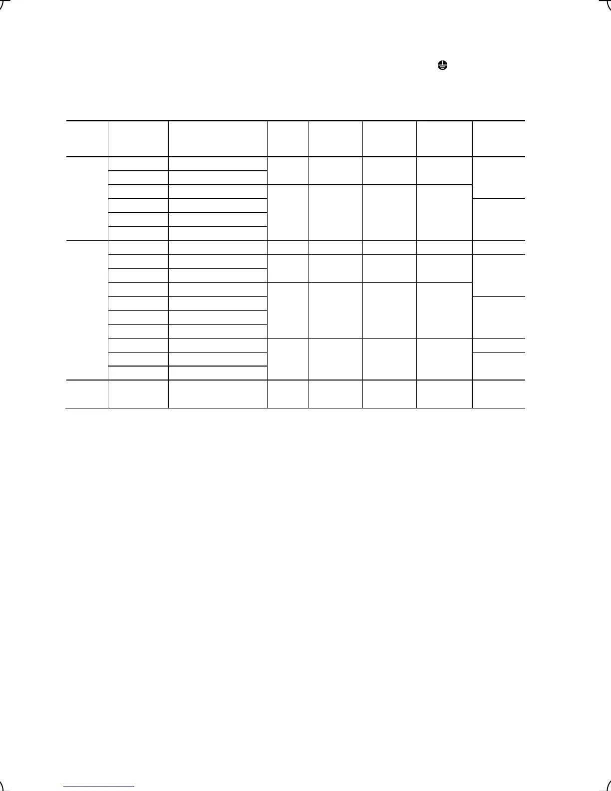
(1) Arrangement of the main circuit terminals
Table 2.6 Main Circuit Terminals
Power
supply
voltage
Applicable
motor rating
(kW)
Inverter type
Terminal
screw
size
Tightening
torque
(N·m)
Grounding
screw size
Tightening
torque
(N·m)
Refer to:
Three-
phase
200 V
5.5 FRN5.5LM1S-2
M5 3.8 M5 3.8
Figure A 7.5 FRN7.5LM1S-2
11 FRN11LM1S-2
M6
(
*
1)
5.8
(
*
1)
M6 5.8
15 FRN15LM1S-2
Figure B
18.5 FRN18.5LM1S-2
22 FRN22LM1S-2
Three-
phase
400 V
3.7 FRN4.0LM1S-4
M4 1.8 M4 1.8 Figure E
5.5 FRN5.5LM1S-4
M5 3.8 M5 3.8
Figure A 7.5 FRN7.5LM1S-4
11 FRN11LM1S-4
M6
(
*
1)
5.8
(
*
1)
M6 5.8
15 FRN15LM1S-4
Figure B
18.5 FRN18.5LM1S-4
22 FRN22LM1S-4
30 FRN30 LM1S-4
M8 13.5 M8 13.5
Figure C
37 FRN37 LM1S-4
Figure D
45 FRN45 LM1S-4
Single-
phase
200 V
2.2 FRN2.2LM1S-7 M4 1.8 M4 1.8 Figure F
(
*
1)
Terminal DB on FRN11-LM1S-2/-4: Screw size M5, Tightening torque 3.8 N·m
Terminal R0, T0 (Common to all types): Screw size M3.5, Tightening torque 1.2 N·m
Note: A box (
) in the above table replaces C (China), E (EU), A (Asia) or J (Japan) depending on the shipping
destination.

 Loading...


