2-8
2.3.2 Removing and retracting the cable guide plate
To secure the protective structure IP20, FRENIC-Lift builds in the cable guide plate for external wiring
connections. To use it follow the steps listed below.
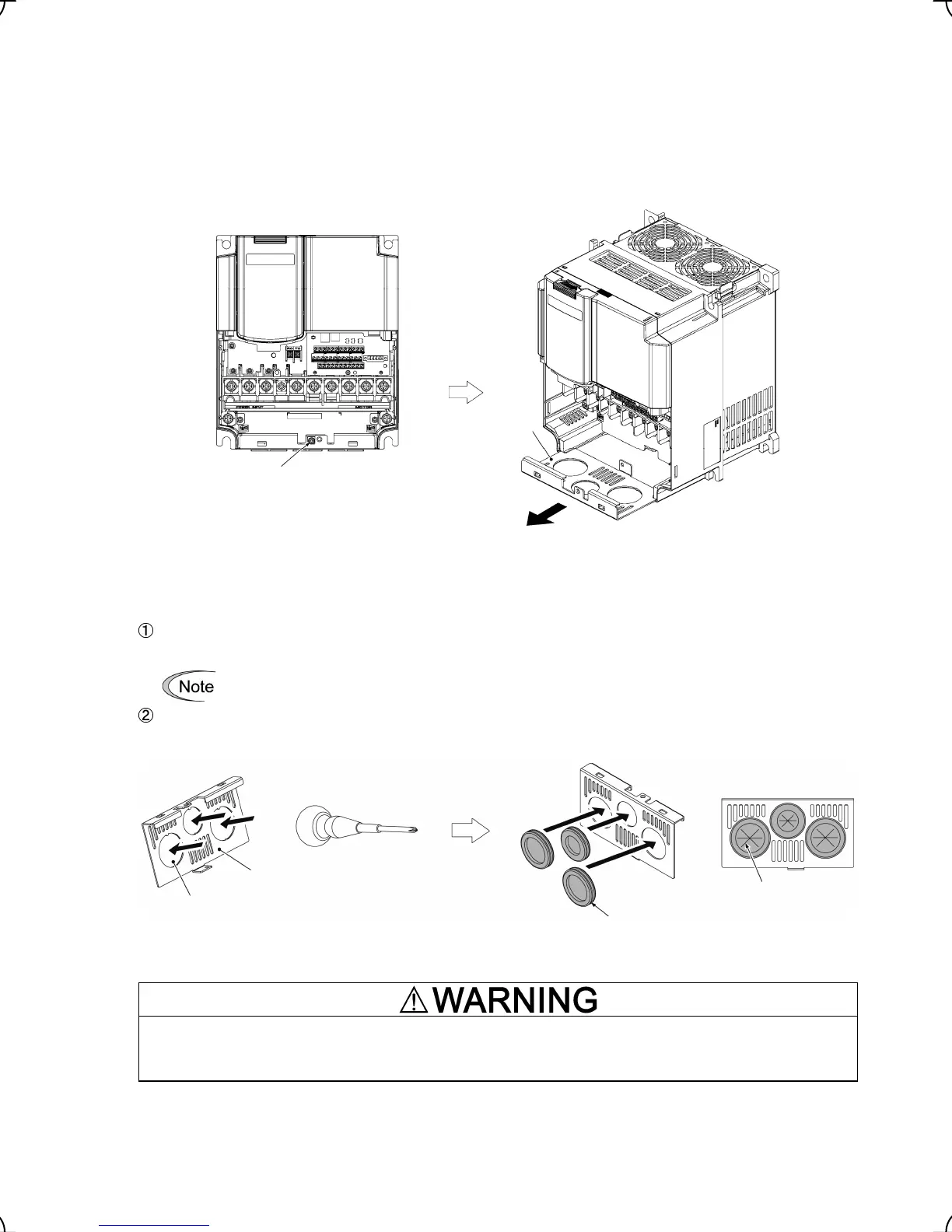
Removing the cable guide plate
Before to proceed, remove the terminal block cover as shown below left.
Remove the screw fastening the cable guide plate, and pull out the plate.
Figure 2.9 Removing the Cable Guide Plate
Opening half-punched holes and mounting rubber bushes
Tap an inside face of the half-punched hole by using a screwdriver grip end or the like to punch it out.
Punch out all 3 holes.
Be careful not to injure yourself by sharp cutting edges of parts.
Set 3 attached rubber bushes in the holes and cut in them by a cutting tool to make cut-outs as shown
below. All cables of an inverter should pass through any of cut-outs
Figure 2.10 Punching out the Holes and Mounting the Rubber Bushes
Be sure to use the rubber bushes. If not, a sharp cutting edge of the cable guide plate hole may damage the cable
sheath. This may induce a short-circuit fault or ground fault.
A fire or an accident may be caused.
Retracting the cable guide plate
Retract the cable guide plate following the steps illustrated in Figure 2.9 in reverse. (Tightening torque: 1.8 N
•
m)
Cable guide plate
fastening screw
Cable
guide
plate
Half-punched
holes
Cable guide plate
ttached rubber bushes
Cut-outs

 Loading...


