7-3
7.3 List of Periodical Replacement Parts
Each part of the product has its own service life that will vary according to the environmental and operating
conditions. It is recommended that the following parts be replaced as specified below.
When the replacement is necessary, contact your Fuji Electric representative.
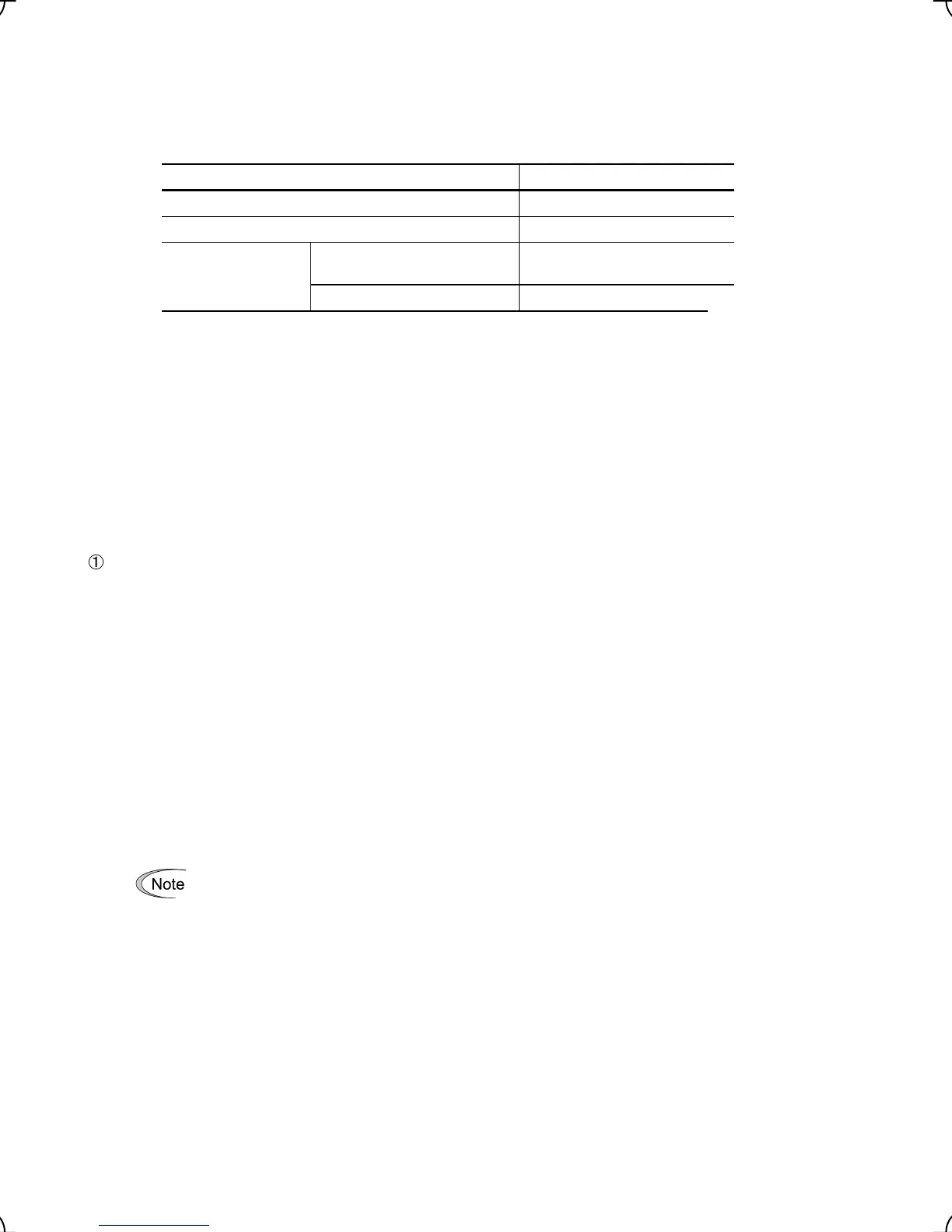
Table 7.2 Replacement Parts
Part name Standard replacement intervals
DC link bus capacitor 7 years
Electrolytic capacitor on the printed circuit board 7 years
Cooling fan
200V series 22kW or below or
400V series 30kW or below
4.5 years
400V series 37kW or above 2.5 years
(Note) These replacement intervals are based on the estimated service life of the inverter at an
ambient temperature of 40℃ in 80% of the rated RMS current. In environments with an
ambient temperature above 40℃ or a large amount of dust or dirt, the replacement intervals
may need to be reduced.
7.3.1 Judgment on service life
(1) Viewing data necessary for judging service life; Measurement procedures
Through Menu 5 "Maintenance Information" in Programming mode, you can view on the optional multi-function
keypad (option) various data (as a guideline) necessary for judging whether key components such as the DC link
bus capacitor, the electrolytic capacitor on the printed circuit board, and the cooling fan are approaching their
service life.
-1 Measuring the capacitance of the DC link bus capacitor (in comparison with that at factory shipment)
Measure the capacitance of the DC link bus capacitor according to the procedure given below. The result will be
displayed on the keypad as a ratio (%) to the initial capacitance at the time of factory shipment.
----------------------------------------------- Procedure for measuring capacitance -----------------------------------------------
1) To ensure validity in the comparative measurement, configure the condition of the inverter as follows.
• Remove the option card (if already in use) from the inverter.
• In case another inverter is connected via the DC link bus to the P(+) and N(-) terminals of the main circuit,
disconnect the wires. (You do not need to disconnect a DC reactor (optional), if any.)
• Disconnect power wires for the auxiliary input to the control circuit (R0, T0).
• If the multi-function keypad is mounted, remove it.
• Turn OFF all the digital input signals fed to terminals [FWD], [REV], [EN], and [X1] through [X8] of the
control circuit.
• If the encoder is wired at terminals (P0, PA, PB, and PZ (if any)), remove it..
• If an external apparatus is attached to terminal [PLC], disconnect it.
• Ensure that transistor output signals ([Y1] ─ [Y4]) and relay output signals ([Y5A/C] and [30A/B/C]) will not
be turned ON.
If negative logic is specified for the transistor output and relay output signals, they are considered
ON when the inverter is not running. Specify positive logic for them.
• Keep the ambient temperature within 25 ±10°C.
2) Switch ON the main circuit power.
3) Confirm that the cooling fan is rotating and the inverter is in stopped state.
4) Switch OFF the main circuit power.
5) Mount the multi-function keypad after five minutes having elapsed, switch ON the main circuit power again.
6) Select Menu 5 "Maintenance Information" in Programming mode and note the reading (relative capacitance
(%) of the DC link bus capacitor).
----------------------------------------------------------------------------------------------------------------------------------------------------

 Loading...


