4-2
4.1.3 Preparation before running the motor for a test--Setting function code data
Before starting running the motor, set function code data specified in Table 4.1 to the motor ratings and your system
design values. For the motor, check the rated values printed on the nameplate of the motor. For your system design
values, ask system designers about them.
To set up function code, you need to use the multi-function keypad (option) or to access their data via
communications link. For details of the multi-function keypad and communications link, refer to the Multi-function
Keypad Instruction Manual (INR-SI47-1092-E) and RS485 Communications FRENIC-Lift Reference Manual
(INR-SI47-1068-E) respectively. For the factory defaults for the motor parameter, refer to the Chapter 5
“ Appendix Factory Defaults ". If the parameter for your motor differs from the default, change it by using the
function code.
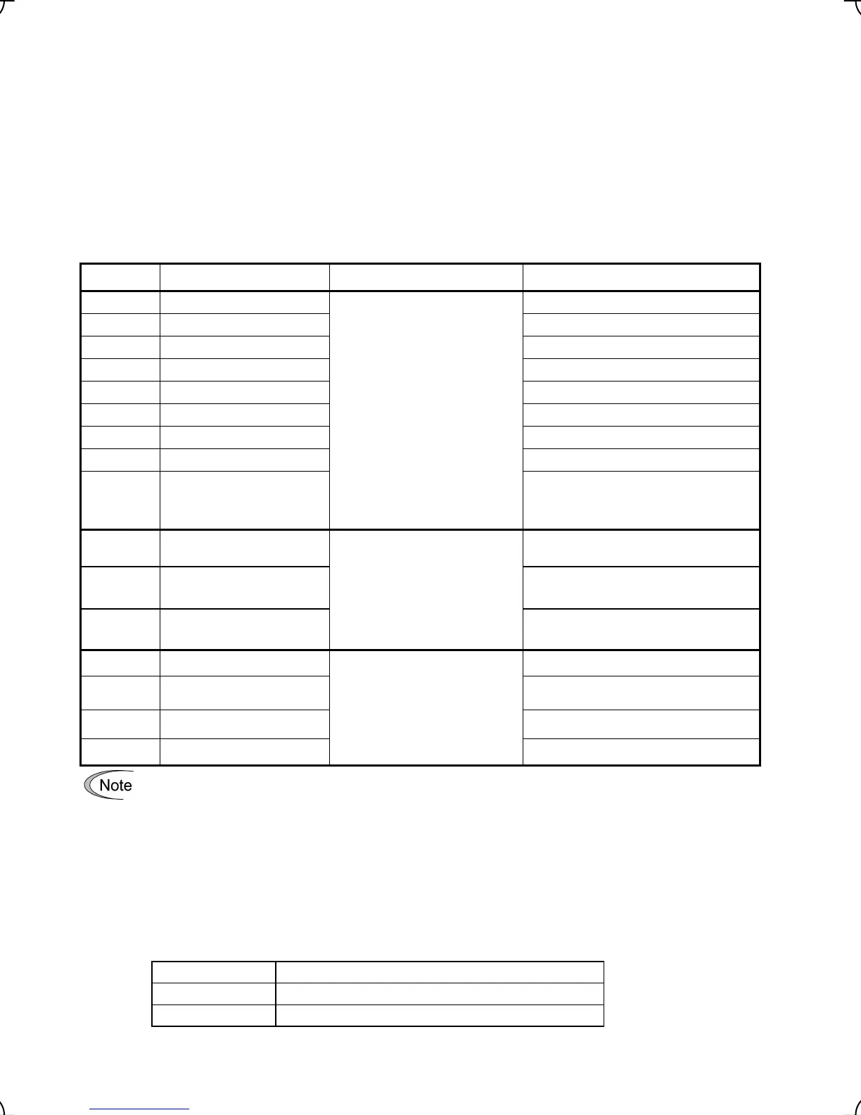
Table 4.1 Settings of Function Code Data before Driving the Motor for a Test
Function code Name Function code data Factory defaults
F04
Rated Speed
Motor ratings (printed on the
nameplate of the motor)
1500 (r/min)
F05
Rated Voltage 190 (V) / 380 (V)
P01
Motor (No. of poles) 4 (P)
P02
Motor (Rated Capacity) Applicable motor rated capacity
P03
Motor (Rated current) Rated current of applicable motor
P06
Motor (No-load current) No load current of the standard motor
P07
Motor (%R1) Primary resistance of the standard motor
P08
Motor (%X) Leakage reactance of the standard motor
P12
Motor (Rated slip)
0.00 (Hz)
*1
*1 The rated slip of the standard motor is
applied.
L01
Pulse Encoder (Selection)
Depending on data sheet of the
pulse encoder.
L01 = 0: 12/15 V complimentary, open
collector output circuit. or 5 V line driver
L02
Pulse Encoder (Resolution)
1024 (p/r)
(pulses/rev)
L04
Magnetic Pole Position Offset
(Offset angle)
0.00 (deg)
F03
Maximum Speed
System design values
* For a test-driving of the motor,
increase values so that they are
longer than your system design
values. If the set time is short,
the inverter may not start
running the motor.
1800 (r/min)
F42
Control Mode
F42 = 0: Vector control with PG (induction
motor)
C21
Speed Command Unit C21 = 0: r/min (Speed data format)
L31
Elevator Parameter (Speed) 60.0 (m/min)
• In any of the following cases, the factory defaults may not produce the best results for auto torque boost,
torque calculation monitoring, or auto energy saving, since the standard settings of motor parameters fo
Fuji motors are not applicable. Tune the motor parameters according to the procedure set forth below.
- The motor to be driven is not a Fuji product or is a non-standard product.
- The cabling between the motor and the inverter is long.
- A reactor is inserted between the motor and the inverter.
• To drive a synchronous motor, you need to tune the inverter for the offset angle of magnet pole before
running the motor.
To drive a synchronous motor, use the option card to be ordered separately.
• Please set the function codes in the following order.
ROM version The setting order
0300, 0500 C21, P02, P01, F03, L31, and other function codes.
Not listed above C21, P01, F03, L31, and other function codes.
Please refer to section 5.1 "Function Codes Requiring Modification".

 Loading...


