7-6
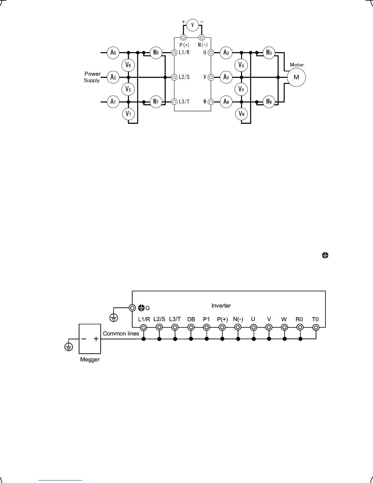
Figure 7.1 Connection of Meters
7.5 Insulation Test
Because an insulation test is made in the factory before shipment, avoid a Megger test.
If a Megger test is unavoidable, follow the procedure below. Because a wrong test procedure will cause breakage
of the inverter, take sufficient care.
A dielectric strength test will cause breakage of the inverter similarly to the Megger test if the test procedure is
wrong. When the dielectric strength test is necessary, contact your Fuji Electric representative.
(1) Megger test of main circuit
1) Use a 500 VDC Megger and shut off the main power supply without fail during measurement.
2) If the test voltage leaks to the control circuit due to the wiring, disconnect all the control wiring.
3) Connect the main circuit terminals with a common cable as shown in Figure 7.2.
4) The Megger test must be limited to across the common line of the main circuit and the ground terminal (
G
).
5) 5 MΩ (1 MΩ for the EMC filter built-in type of inverters) or a larger value displayed at the Megger indicates a
correct state. (The value is for a discrete inverter.)
Figure 7.2 Megger Test
(2) Dielectric strength test of control circuit
Do not perform a Megger test or dielectric strength test for the control circuit. Prepare a high resistance range
tester for the control circuit.
1) Disconnect all the external wiring from the control circuit terminals.
2) Perform a continuity test to the ground. 1 MΩ or a larger measurement indicates a correct state.
(3) Dielectric strength test of external main circuit and sequence control circuit
Disconnect all the inverter terminals so that the test voltage is not applied.

 Loading...


