Page 1-2 G1000 V8.XX S/W Load and Post Install Checkout – Columbia 350/400
Revision 1 190-00577-04
• verify software loads in accordance with section 2.6
• reconfigure optional systems and verify setup items in accordance with section 2.7
• perform the Final System Checkout in accordance with section 3
• perform the GFC System Checkout in accordance with section 4
1.4 Post Installation Process
Section 2:
Software and system configuration loading procedures. Manual configuration items are also
addressed. At the end, all software versions and part numbers are verified against the Required
Equipment List (REL), Columbia Part Number RB011002.
Section 3:
Ground checks include exercising and testing basic G1000 functions, calibrating the AHRS, and
conducting a final systems checkout.
Section 4:
Detailed GFC 700-specific ground checks are given in this section.
1.5 System Description
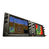
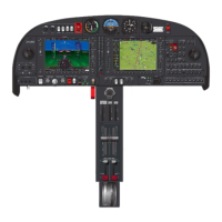
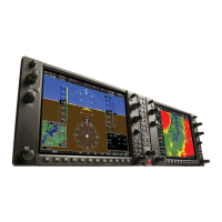
The G1000 avionics system is comprised of the following Line Replaceable Units (LRUs):
• One GDU 1040 (Primary Flight Display)
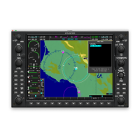
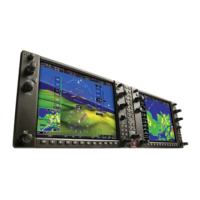
• One GDU 104X (Multi-function Flight Display)
• Two GIA 63/63W Integrated Avionics Units
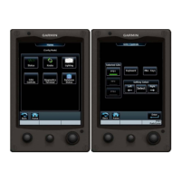
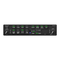
• GCU 476 Remote Keypad
• GEA 71 Engine and Airframe Unit
• GDC 74A Air Data Computer (ADC)
• GTP 59 Outside Air Temperature (OAT) Probe
• GRS 77 Attitude & Heading Reference System (AHRS)
• GMU 44 Magnetometer
• GMA 1347 Audio System with integrated Marker Beacon Receiver
• GTX 33 Mode S Transponder
• GDL 69A XM Data Link Receiver
• GSA 81 Servos (Pitch and Roll)
• GTA 82 Pitch Trim Adapter
• Data base cards for the PFD and MFD
In addition, there are four Configuration Modules (one each for the GDU 1040 PFD, GEA 71, GDC 74A
and the GRS 77).
The following equipment, systems and sensors interface to the G1000 avionics systems:
• Existing Manifold Pressure sensor
• Existing Tachometer sensor
• Existing Oil pressure sensor and low pressure switch
• Existing Oil temperature sensor
• Existing Cylinder Head Temperature (CHT) sensors
• Exhaust Gas Temperature (EGT) sensors
• Existing Turbine Inlet Temperature (TIT) sensors (Columbia 400 only)
• Existing Fuel Level sensors (four)
• Existing low fuel switches (L and R)
• Existing fuel selector position switches
• Existing Fuel Flow sensor
• Existing Electrical System sensors and alternator inop switches
 Loading...


