Page 3-26 G1000 V8.XX S/W Load and Post Install Checkout – Columbia 350/400
Revision 1 190-00577-04
19. On the MFD, select the 4
th
AUX page and change the COM channel spacing back to 25 kHz.
3.6.2 VOR/LOC/GS Test
Check the VOR, ILS, and Glideslope functions with ramp test equipment. Operate the equipment
according to the test equipment manufacturer’s instructions. Adjust the RF signal to a level adequate to
perform the test. Select the appropriate HSI source by using the CDI softkey.
NOTE
The PFD HSI does not show a course deviation bar unless a valid VHF nav frequency is
tuned.
Simulate a VOR signal on radial 000° with a course-width of 20°. Verify full scale deflection of the CDI
while applying a 10° deviation signal. Exercise the CDI with both right and left deviations for both NAV
1 and 2. Exercise the Glideslope deviation indicator with up and down deviation indications.
3.6.3 COM Antenna VSWR Checks
Check for insertion loss and VSWR (Voltage Standing Wave Ratio). VSWR should be checked with an
in-line type VSWR/wattmeter inserted in the coaxial transmission line between the transceiver and the
antenna. The VSWR should be inserted as close to the transceiver as possible. Any problem with the
antenna installation is most likely seen as high reflected power. A VSWR of 3:1 may result in up to a
50% loss in transmit power. Ideally, the VSWR should be 2.5:1 or less.
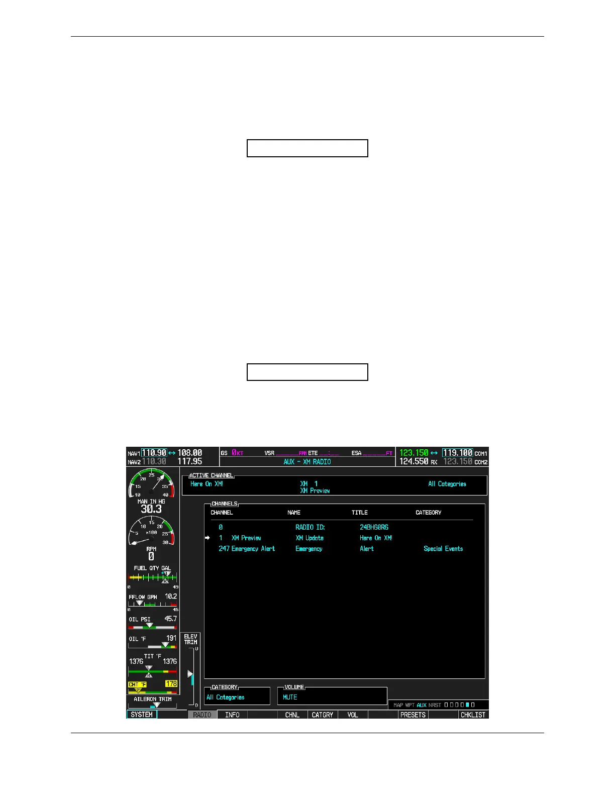
3.7 GDL 69 Testing
NOTE
This section verifies correct installation in the aircraft. It does not activate the GDL 69
XM data link radio. If the XM Radio is activated, the channel list will contain more
channels than the three that are shown for a radio that has not been activated. Complete
instructions for activating the XM data link can be found in document 190-00355-04.

 Loading...


