Garmin G5 Install Manual & Pilot's Guide
190-02072-00 Rev. E 171
Pilot's Guide
Installation Manual Pilot's Guide Appendix Index
2.8 NAVIGATION
A G5 installed as part of a G3X system with multiple navigation sources will only
display data from the #1 navigation source. If the navigation source is a GNS/GTN
unit, both GPS and VLOC data can be displayed. Displayed navigation information is
also dependent upon the selection on the navigation configuration page.
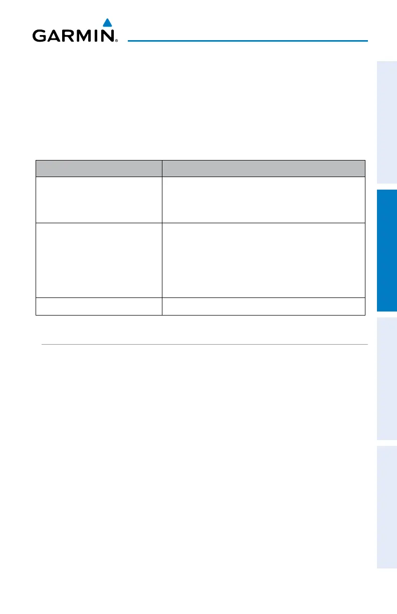
Table 2-1 Navigation Data Functions
Installation Type Setting Navigation Data Behavior
G3X System Backup (with
Navigation Data configuration
mode set to Always Display)
Always displays navigation data.
G3X System Backup (with
Navigation Data configuration
mode set to Auto)
Displays navigation data only when the
navigation data source selected on the G3X PFD
is the same as the navigation data available to
the G5. (If no G3X displays are present, this will
function as if Navigation Data is set to Always)
Standalone Instrument
Always displays navigation data
2.8.1 COURSE DEVIATION INDICATOR (CDI)
The PFD Page displays the Course Deviation Indicator (CDI) below the slip/skid
indicator. The HSI Page displays the CDI on the Horizontal Situation Indicator.
The Course Deviation Indicator (CDI) move left or right along a lateral deviation
scale to display the aircraft position relative to the course. If the course deviation data
is not valid, the CDI is not displayed.
The CDI is capable of displaying two sources of navigation: GPS or NAV (VOR,
localizer) depending on the external navigator configured (refer to the Installation
Manual section for more information). Color indicates the current navigation source:
magenta (for GPS) or green (for VOR and LOC). The full-scale limits for the CDI are
defined by a GPS-derived distance when coupled to GPS. When coupled to a VOR or
localizer (LOC), the CDI has the same angular limits as a mechanical CDI.

 Loading...


