Garmin G5 Install Manual & Pilot's Guide
190-02072-00 Rev. E
36
Unit Installation
Installation ManualPilot's GuideAppendixIndex
1.5 G5 PINOUT
Use the information in this section (along with other applicable sections/appendices
in this document) to construct the wiring required for the G5 installation.
Connector references used throughout this document use the prefixes "J" (Jack) and
"P" (Plug). "J" refers to the the connector on the LRU, and "P" refers to the connector
on the wiring harness. "J" and "P" designate the connector only, regardless of the
contact type (pin or socket).
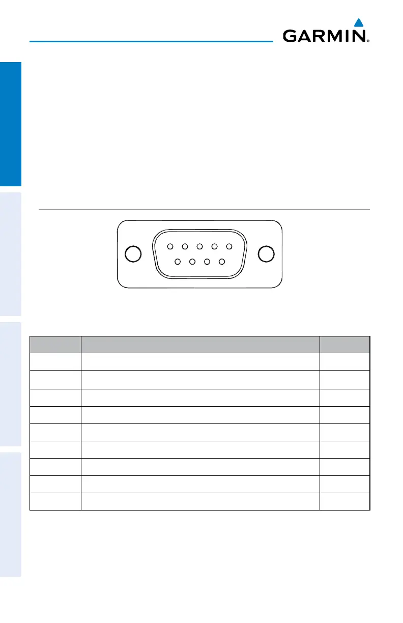
1.5.1 J51
51
96
Figure 1-21 J51 on the G5
Table 1-11 J51 Pin Descriptions
Pin Pin Name I/O
1 CAN-H I/O
2 CAN-L I/O
3 UNIT ID In
4 RS-232 RX 1 In
5 RS-232 TX 1 Out
6 SIGNAL GROUND --
7 AIRCRAFT POWER 1 In
8 AIRCRAFT POWER 2 In
9 POWER GROUND --

 Loading...


