Garmin G5 Install Manual & Pilot's Guide
190-02072-00 Rev. E
54
Unit Installation
Installation ManualPilot's GuideAppendixIndex
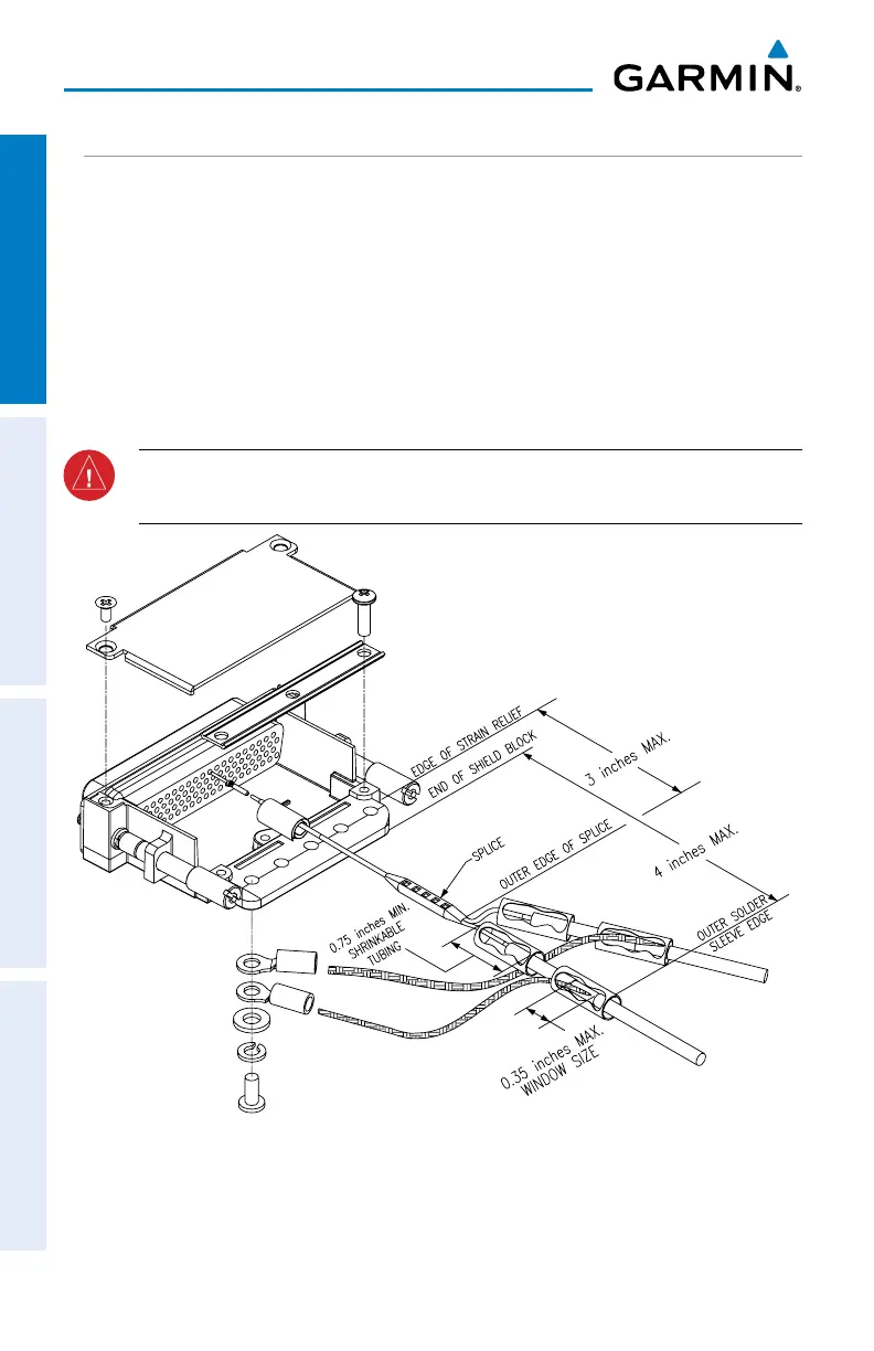
1.6.8 SPLICING SIGNAL WIRES
Figure 1-29 shows an example two wire splice. Note that the splice must be made
within 3 inches of the Shield Block. A signal wire should be spliced into a maximum
of three wires. This wire splicing technique can be used with all the shield termination
methods outlined in the previous sections. The following wire splice parts are
recommended:
• Raychem D-436-36/37/38
• MIL-SPEC MIL-S-81824/1
WARNING: Keep the splice out of the backshell for pin extraction, and
outside of the strain relief to avoid preloading.
Figure 1-29 D-Sub Spliced Signal Wire Example

 Loading...


