2.5 Electrical Installation
This section contains detailed instructions for wiring the
adjustable frequency drive. The following tasks are
described.
•
Wiring the motor to the adjustable frequency drive output terminals
•
Wiring the AC line power to the adjustable frequency drive input terminals
•
Connecting control and serial communication wiring
•
After power has been applied, checking input and motor power; programming control terminals for their intended
functions
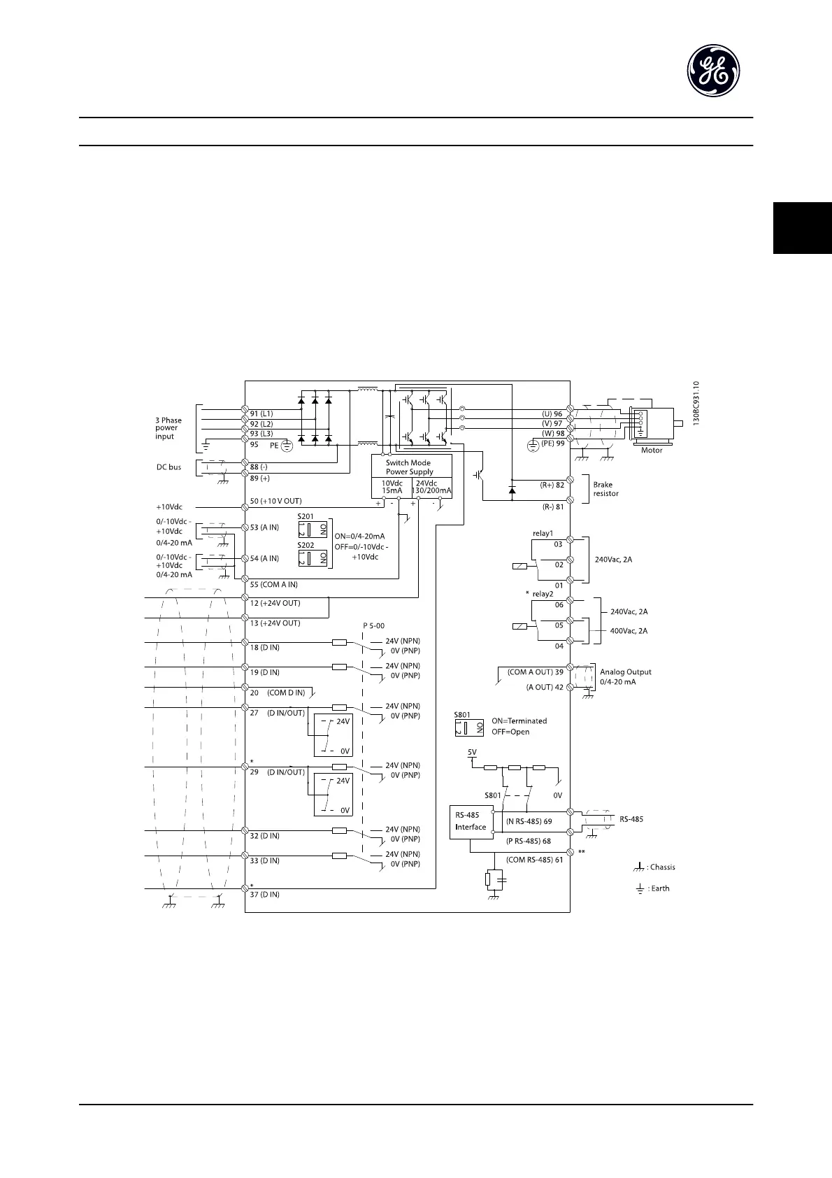
Figure 2.12 Basic Wiring Schematic Drawing
A=Analog, D=Digital
Terminal 37 is used for Safe Stop. For Safe Stop installation
instructions, refer to the Design Guide.
*The brake chopper factory option must be ordered to use
dynamic braking resistors.
**This is available when ordering the brake chopper option
on unit size 23 and above drives.
Installation
AF-650 GP
TM
Design and Installation Guide
DET-767A 2-7
2

 Loading...


