•
Torque terminals in accordance with the
information provided in 12 Terminal and
Applicable Wire
•
Follow the motor manufacturer wiring
requirements
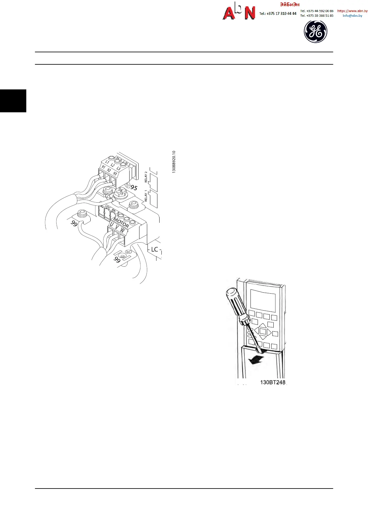
Figure 2.15 represents line power input, motor, and ground
grounding for basic adjustable frequency drives. Actual
configurations vary with unit types and optional
equipment.
Figure 2.15 Example of Motor, Line Power and Ground Wiring
2.5.4 AC Line Power Connection
•
Size wiring based upon the input current of the
adjustable frequency drive. For maximum wire
sizes, see Table 12.1.
•
Comply with local and national electrical codes
for cable sizes.
•
Connect 3-phase AC input power wiring to
terminals L1, L2, and L3 (see Figure 2.15).
•
Depending on the configuration of the
equipment, input power will be connected to the
line power input terminals or the input
disconnect.
•
Ground the cable in accordance with grounding
instructions provided in 2.5.2 Grounding
Requirements
•
All adjustable frequency drives may be used with
an isolated input source as well as with ground
reference power lines. When supplied from an
isolated line power source (IT line power or
floating delta) or TT/TN-S line power with a
grounded leg (grounded delta), set SP-50 RFI Filter
to [0] Off. When off, the internal RFI filter
capacitors between the chassis and the
intermediate circuit are isolated to avoid damage
to the intermediate circuit and to reduce ground
capacity currents in accordance with IEC 61800-3.
2.5.5 Control Wiring
•
Isolate control wiring from high power
components in the adjustable frequency drive.
•
If the adjustable frequency drive is connected to
a thermistor, for PELV isolation, optional
thermistor control wiring must be reinforced/
double insulated. A 24 V DC supply voltage is
recommended.
2.5.5.1 Access
•
Remove access cover plate with a screw driver.
See Figure 2.16.
•
Or remove front cover by loosening attaching
screws. See Figure 2.17.
Tightening torque for front cover is 2.0 Nm for
unit size 15 and 2.2 Nm for unit sizes 2X and 3X.
Figure 2.16 Control Wiring Access for IP20/Open chassis
enclosures
Installation
AF-650 GP
TM
Design and Installation Guide
2-10 DET-767A
2

 Loading...


