In the configuration shown in Figure 6.5, H-41 Motor
Control Principle is set to [1] Advanced Vector Control and
H-40 Configuration Mode is set to [0] Speed open-loop. The
resulting reference from the reference handling system is
received and fed through the ramp limitation and speed
limitation before being sent to the motor control. The
output of the motor control is then limited by the
maximum frequency limit.
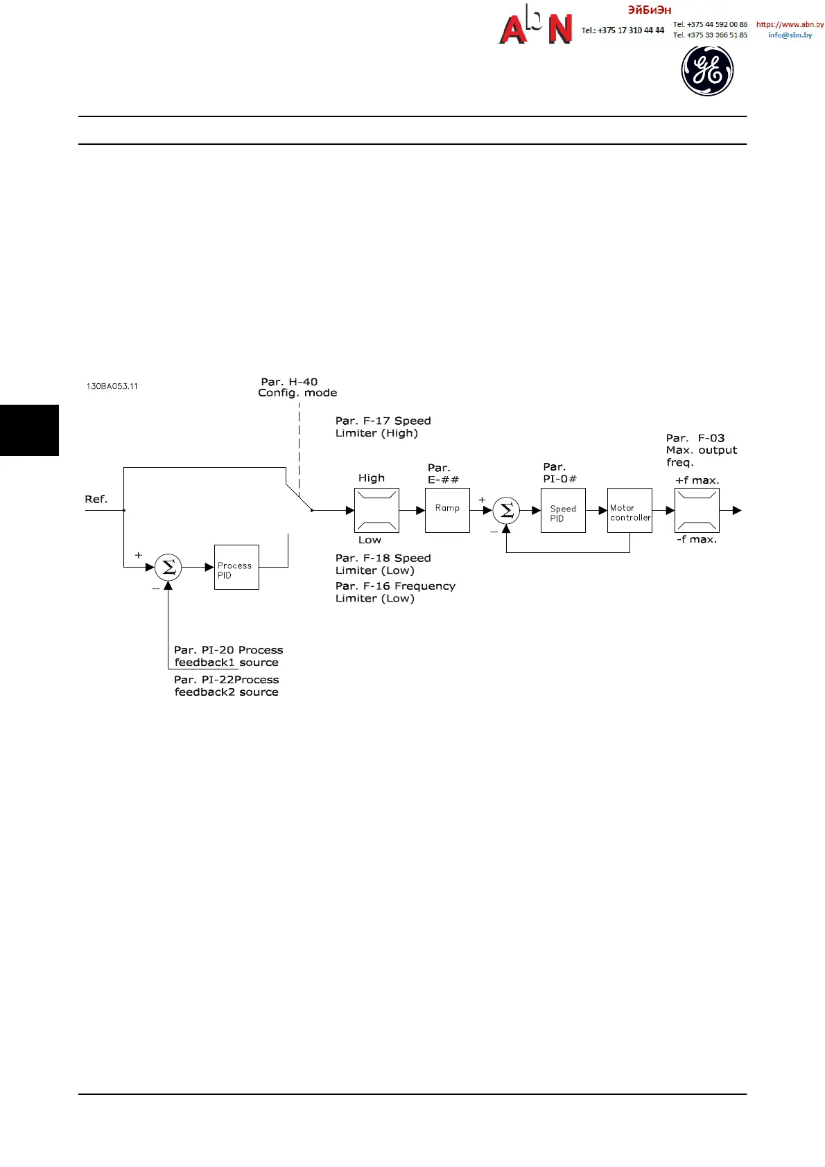
If H-40 Configuration Mode is set to [1] Speed closed-loop
the resulting reference will be passed from the ramp
limitation and speed limitation into a speed PID control.
The Speed PID control parameters are located in parameter
group PI-0#. The resulting reference from the speed PID
control is sent to the motor control limited by the
frequency limit.
Select [3] Process in H-40 Configuration Mode to use the
process PID control for closed-loop control of, e.g. speed
or pressure in the controlled application. The Process PID
parameters are located in parameter group PI-2# and PI-3#.
6.3.3 Control Structure in Flux Sensorless
Figure 6.6 Control Structure in Flux Sensorless Open-loop and Closed-loop Configurations
In the configuration shown, H-41 Motor Control Principle is
set to [2] Flux sensorless and H-40 Configuration Mode is set
to [0] Speed open-loop. The resulting reference from the
reference handling system is fed through the ramp and
speed limitations as determined by the parameter settings
indicated.
An estimated speed feedback is generated to the speed
PID to control the output frequency.
The Speed PID must be set with its P, I, and D parameters
(parameter group PI-0#).
Select [3] Process in H-40 Configuration Mode to use the
process PID control for closed-loop control of, e.g. speed
or pressure in the controlled application. The Process PID
parameters are found in parameter group PI-2# and PI-3#.
Application Setup Examples
AF-650 GP
TM
Design and Installation Guide
6-8 DET-767A
6

 Loading...


