6.4.5 Scaling of Analog and Pulse
References and Feedback
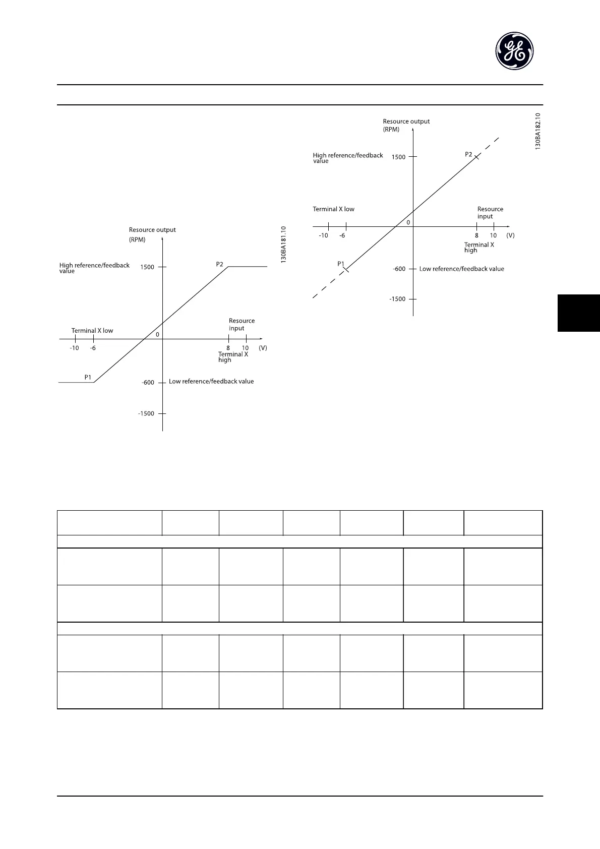
References and feedback are scaled from analog and pulse
inputs in the same way. The only difference is that a
reference above or below the specified minimum and
maximum “endpoints” (P1 and P2 in Figure 6.15) are
clamped whereas a feedback above or below is not.
Figure 6.15 Scaling of Analog and Pulse References and
Feedback
Figure 6.16
The endpoints P1 and P2 are defined by the following parameters, depending on which analog or pulse input is used
Analog 53
S201=OFF
Analog 53
S201=ON
Analog 54
S202=OFF
Analog 54
S202=ON
Pulse Input 29 Pulse Input 33
P1 = (Minimum input value, Minimum reference value)
Minimum reference value AN-14 Termina
l 53 Low Ref./
Feedb. Value
AN-14 Terminal
53 Low Ref./
Feedb. Value
AN-24 Termina
l 54 Low Ref./
Feedb. Value
AN-24 Terminal
54 Low Ref./
Feedb. Value
E-62 Term. 29
Low Ref./Feedb.
Value
E-67 Term. 33 Low
Ref./Feedb. Value
Minimum input value AN-10 Terminal
53 Low Voltage
[V]
AN-12 Terminal
53 Low Current
[mA]
AN-20 Termina
l 54 Low
Voltage [V]
AN-22 Terminal
54 Low Current
[mA]
E-60 Term. 29
Low Frequency
[Hz]
E-65 Term. 33 Low
Frequency [Hz]
P2 = (Maximum input value, Maximum reference value)
Maximum reference value AN-15 Termina
l 53 High Ref./
Feedb. Value
AN-15 Terminal
53 High Ref./
Feedb. Value
AN-25 Termina
l 54 High Ref./
Feedb. Value
AN-25 Terminal
54 High Ref./
Feedb. Value
E-63 Term. 29
High Ref./
Feedb. Value
E-68 Term. 33 High
Ref./Feedb. Value
Maximum input value AN-11 Termina
l 53 High
Voltage [V]
AN-13 Terminal
53 High Current
[mA]
AN-21 Termina
l 54 High
Voltage[V]
AN-23 Terminal
54 High
Current[mA]
E-61 Term. 29
High Frequency
[Hz]
E-66 Term. 33 High
Frequency [Hz]
Table 6.14
Application Setup Examples
AF-650 GP
TM
Design and Installation Guide
DET-767A 6-13
6

 Loading...


