local operation. Also included are the status
indicator lights.
d. Operational mode keys and reset.
4.1.2 Setting Keypad Display Values
The display area is activated when the adjustable
frequency drive receives power from AC line voltage, a DC
bus terminal, or an external 24 V supply.
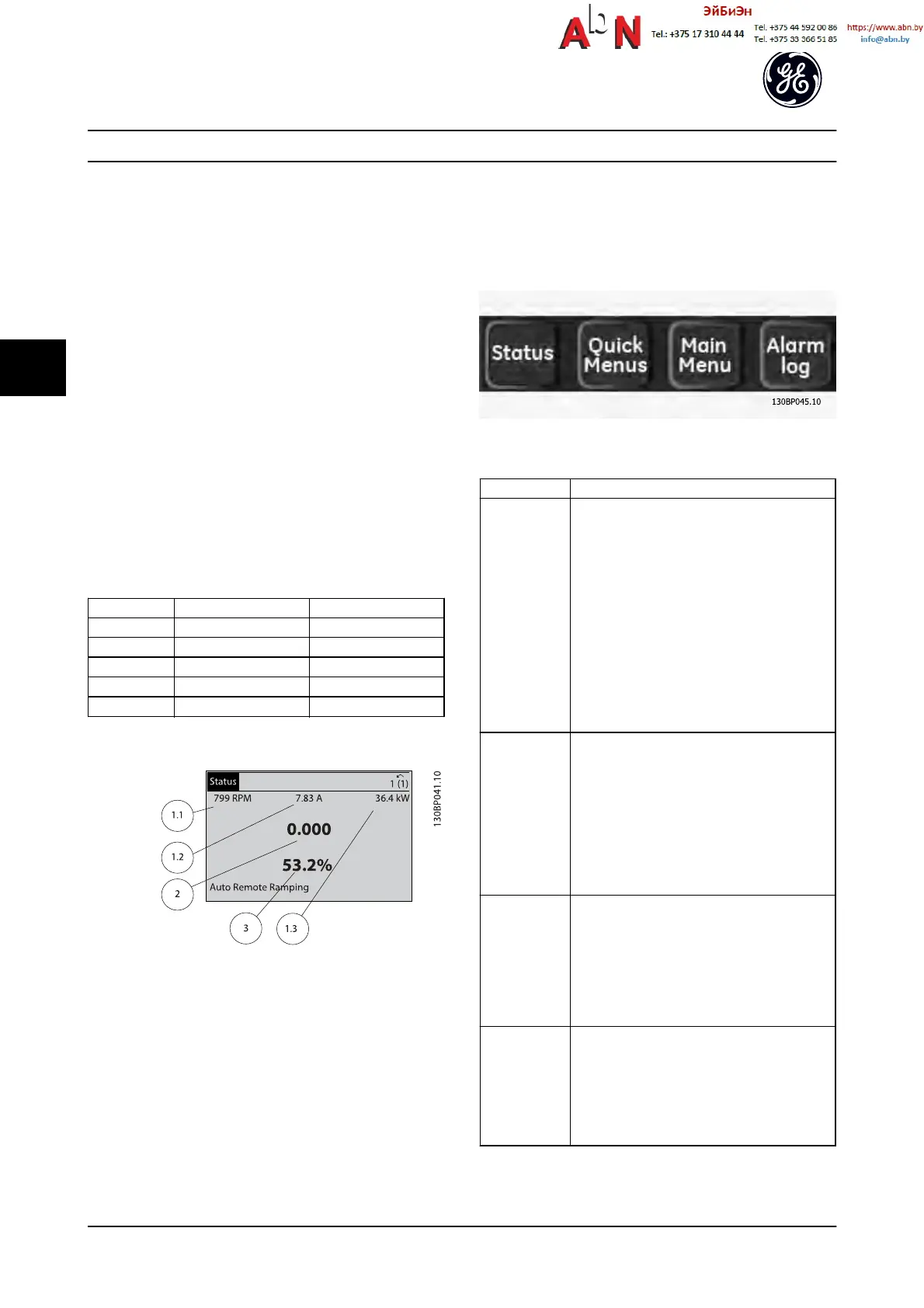
The information displayed on the keypad can be
customized for user application.
•
Each display readout has a parameter associated
with it.
•
Options are selected in the menu Keypad Set-up.
•
Display 2 has an alternate larger display option.
•
The adjustable frequency drive status at the
bottom line of the display is generated automat-
ically and is not selectable.
Display Parameter number Default setting
1.1 K-20 Motor RPMs
1.2 K-21 Motor current
1.3 K-22 Motor power (kW)
2 K-23 Motor frequency
3 K-24 Reference in percent
Table 4.1
Figure 4.2
4.1.3 Display
Menu keys are used for menu access for parameter set-up,
toggling through status display modes during normal
operation, and viewing fault log data.
Figure 4.3
Key Function
Status Shows operational information.
•
In auto mode, press to toggle between
status readout displays.
•
Press repeatedly to scroll through each
status display.
•
Press [Status] plus [
▲
] or [
▼
] to adjust the
display brightness.
•
The symbol in the upper right corner of the
display shows the direction of motor
rotation and which set-up is active. This is
not programmable.
Quick Menu Allows access to programming parameters for
initial set-up instructions and many detailed
application instructions.
•
Press to access Quick Start for sequenced
instructions to program the basic frequency
controller setup
•
Follow the sequence of parameters as
presented for the function set-up
Main Menu Allows access to all programming parameters.
•
Press twice to access top-level index
•
Press once to return to the last location
accessed.
•
Press to enter a parameter number for
direct access to that parameter.
Alarm Log Displays a list of current warnings, the last 10
alarms, and the maintenance log.
•
For details about the adjustable frequency
drive before it entered the alarm mode,
select the alarm number using the
navigation keys and press [OK].
Table 4.2
User Interface
AF-650 GP
TM
Design and Installation Guide
4-2 DET-767A
4

 Loading...


