Chapter 2: Installation
Concord 4 Installation Manual 21
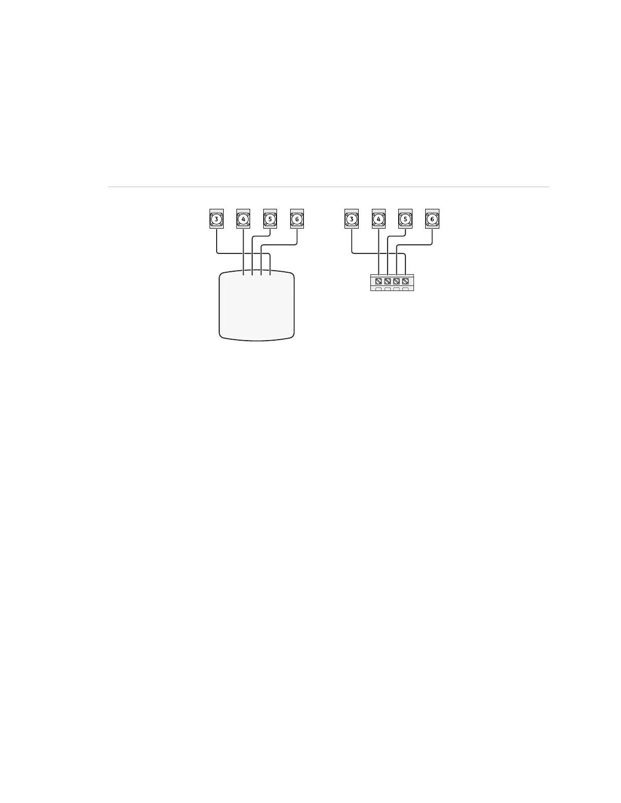
SuperBus 2000 touchpads
SuperBus 2000 touchpads may have wires or screw terminals. All use the same
wiring scheme for power and bus connections. Connect touchpads as shown in
Figure 14 below.
Figure 14: Connecting touchpads
Panel terminals
Touchpad with wires
Touchpad with terminals
GND +12V A BUS B GND +12V A BUS B
+12V - Red
A
+12V
B
GND/COM
BUS A - Green
BUS B - White or Yellow
GND - Black
SuperBus 2000 modules
You may install SuperBus 2000 modules inside the panel cabinet or away from the
panel in the enclosure provided with the module.
Mounting modules inside the panel enclosure
Use the following guidelines when mounting modules inside the panel enclosure
(Figure 15 on page 22):
• Up to four of the SuperBus 2000 modules listed in
Table 3 on page 3 can be
mounted inside the cabinet.
• The 2-amp power supply and phone interface/voice module each use two
mounting spaces when mounted inside the panel enclosure.
• The panel includes two support standoffs you install to secure module bookplates
to the panel.
Even if you don’t plan to mount modules inside the cabinet, install the support
standoffs for future use and to avoid losing them.
The cabinet has built-in mounting clips on the top and sides that module backplates
slide onto for mounting.
 Loading...