2018112-003 Rev J eBike, eBike L, eBike EL - 25 -
B: Mechanical Design
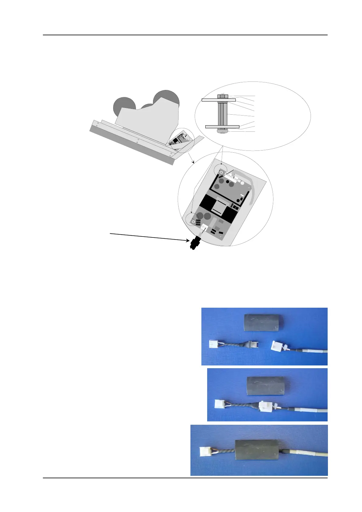
B-3.1.4 eBike L: Install Power Supply Module for eBike L (P/N 2018111-142)
Replacement of large power supply ERS80US24M or small power supply EMC60US24.
When replacing the power supply, it is mandatory to replace the supplied connection cable as well.
The area below the lock washers at the holes where
the metal standoffs are screwed in must be cleared
of any coating. Use a round file or a drill with a
diameter of 4.1 mm to remove the coating from
the hole.
Wrap the supply and adapter cables
together in heat-shrink tubing.
The connectors on power supply are not compatible with those of the previous power supplies.
The entire connection cable between power supply and IFP board (24VDC, secondary) is replaced.
An adapter cable must be attached to the connection cable between the modular connector and the power
supply (230VAC, primary).
It is absolutely mandatory to secure the connection between the adapter and the cable inside the device with
the shrink tubing supplied.
Supplied material
1 x adapter cable
1 x shrink tubing Ø18mm, length 50mm
1. Connect adapter to cable
Important: the catch must lock into place
2. Slip the shrink tubing over the connection
PE
PE
PE
PE
Nut M3
Washer 3.2
Power supply board
Lock washer 3.2
Standoff M3 12mm
Holding plate power supply
Lock washer 3.2
Fillister head screw M3x8
 Loading...