- 78 - eBike, eBike L, eBike EL 2018112-003 Rev J
Appendix A: Interfaces
A.3 Analog Interfaces With Digital Data Transfer
For analog load control from EKG unit and automatic, digital data communication with EKG unit
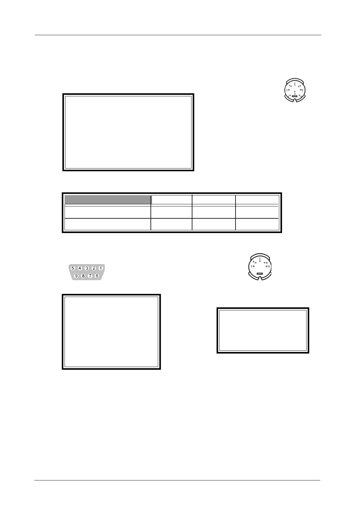
• ANALOG: Pin configuration (view of connector):
ANALOG
Pin 1 External load (input)
Pin 2 -
Pin 3 Remote start EKG unit (output)
Pin 4 -
Pin 5 Load output
Pin 6 -
Pin 7 -
Pin 8
Enclosure GND
• Voltages:
Analog minimum maximum resolution
set load (input) 0 V +10 V DC adjustable
set load (output) 0 V +10 V DC adjustable
• PORT 1 or PORT 3: Pin configuration, digital (view of connector):
PORT 1 PORT 3
Pin 1 -
Pin 2 Receive (Input)
Pin 3 Transmit (Output) Pin 1 TxD
Pin 4 - Pin 2 GND
Pin 5 GND PIN 3 -
Pin 6 - Pin 4 -
Pin 7 - Pin 5 RxD
Pin 8remote start EKG unit
Pin 9 -
• Transmission Protocol:
With the Analog setting, the system responds to a digital request by sending a standardized data
record. The string consists of 54 alphanumeric characters as well as of Carriage Return and Line
Feed as end-of-line characters. Via the RS232 interface, only the command S <CR> is accepted, all
other characters are ignored. The exercise test cannot be terminated by sending a command to the
interface. BP values will read “000” in the data string to indicate erroneous BP measurements.
The command S <CR> initiates a BP measurement. Upon termination of the BP measurement, the
ergometer outputs the data record.
No.xx, SYST:xxx mmHg, DIAST: xxx mmHg, Pulse: xxx/min <CR> <LF>
where No.xxis used to identify the consecutive BP measurements (No.01, No.02, ...).
 Loading...