2018112-003 Rev J eBike, eBike L, eBike EL - 41 -
C: Electrical Design
PCB Interface
(= PCBIF)
1
X200
20
X201
1
X1
1
1
X152
1
X151
1
X155
1
X154
1
X150
1
X153
b
external speed
indication (RPM)
(eBike EL external
terminal only)
control terminal with
* LCD
* LCD control
* NIBP module
SERVICE
Port 3 (5-pin DIN socket)
ANALOG (8-pin DIN socket)
not connected
not connected
Port 1 (9-pin SUB-D)
Port 2 (9-pin SUB-D)
Assigment: see Interfaces
a
Power
NIBP
saddle motor
saddle height
sensor
control
terminal
saddle height
indication
PCBRMP
Port
3
ANA
LOG
SERVICE
PORT 2
PORT 1
BP Module
pneumatic
autoranging
power supply
100-240 VAC,
50-60 Hz
strain gauge
a backup battery
b DIP switch
ON / OFF
1 electric/mechanic
saddle height adjustment
2 user-specific
3 NIBP / no NIBP module
4 user-specific
5 ON / ---
6 couch ergometer / bicycle ergometer
processor
μμ
μμ
μC
trimmer
strain
gauge
strain
gauge
PCB RPM
(= PCBRPM)
cable connection
drive unit
4 J5 1
1
J3
20
RPM
sensor
red
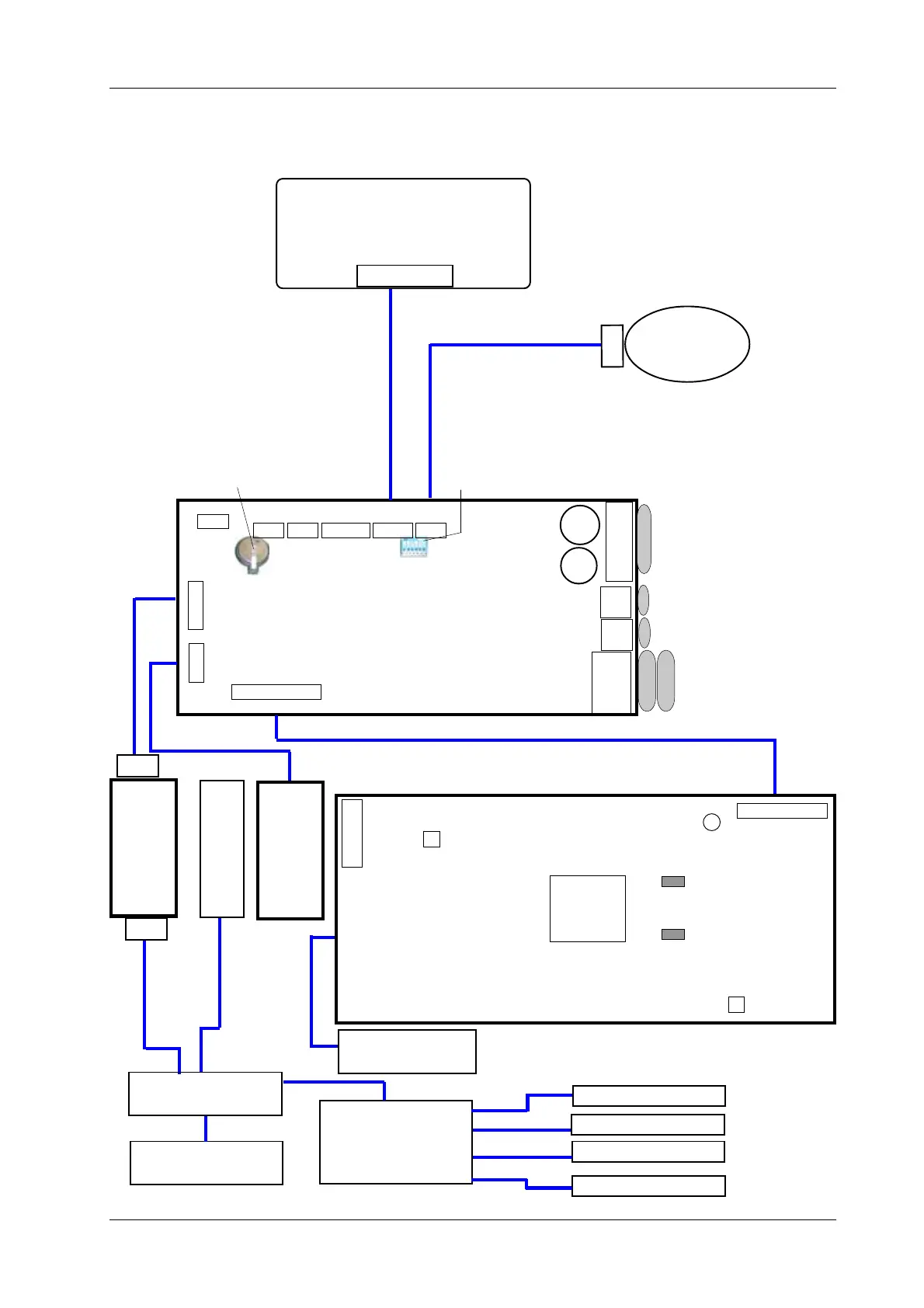
Figure C-5: Block Diagram eBike EL for RPM Board 1
91
18
X81 10
26 19
51
9
X170
6
51
96
28
1
X22
7
28
1
X20
7
blue
ON/OFF switch
J1
J2
X1
X2 to X7
motor control
eBike EL
230 V AC
or
120 V AC
saddle motor
motor, longitudinal
remote control
power connector
modular connector
SUB-D connector
3 3
1
1
C-1.5 Block Diagram eBike EL for RPM Board 1
2 2
motor, lateral tilt
 Loading...