2018112-003 Rev J eBike, eBike L, eBike EL - 65 -
Part E: Drive Unit
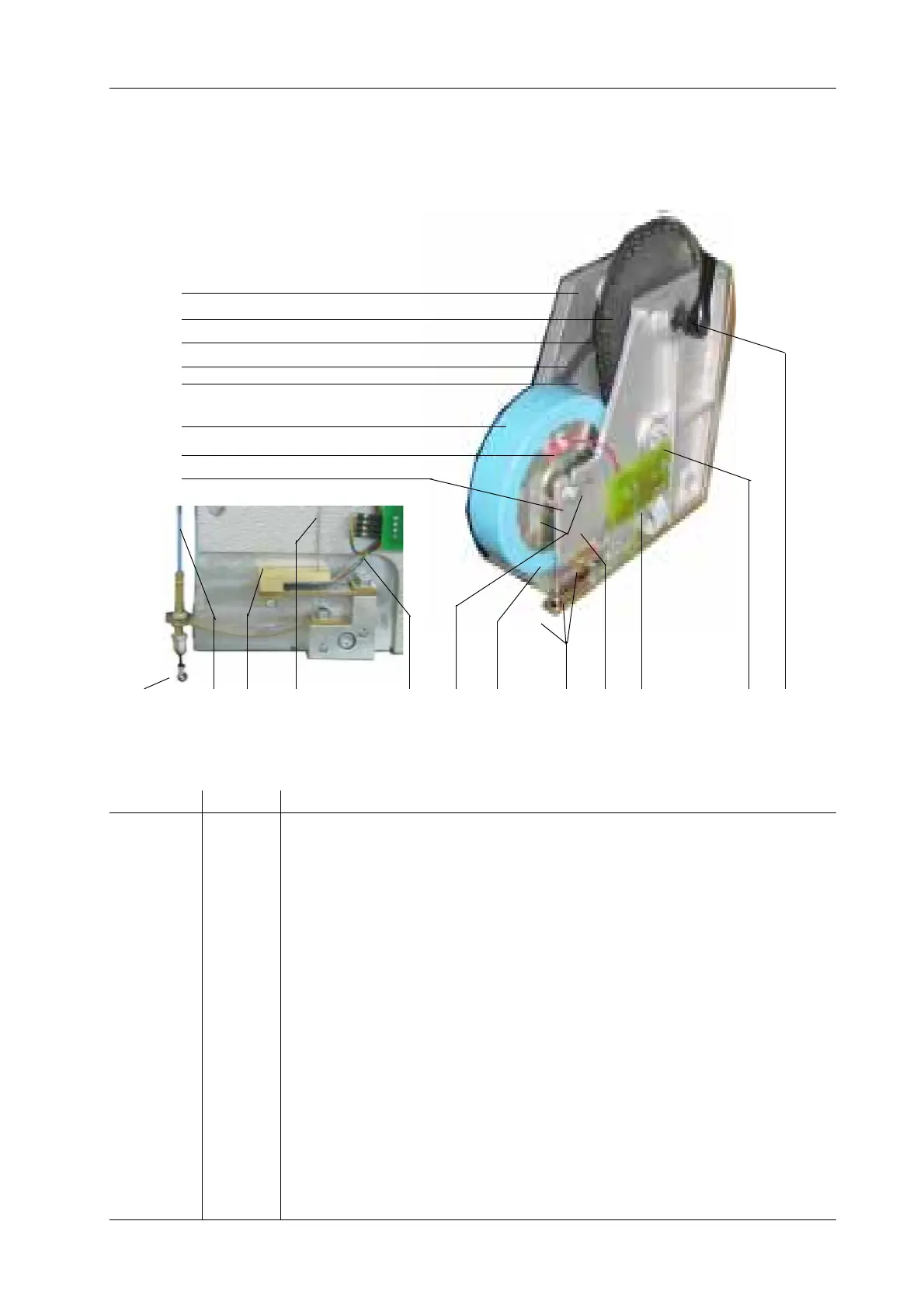
E-1. Drive Unit - Mechanical Design
1-19 1-16 1-14 1-15 1-18 1-17 1-16 1-14 1-15 1-11 1-10 1-9
Figure E1: Mechanical Overview: Load Unit with PCB RPM and Strain Gauge
Item No. Part No. Description
1-1 - Aluminum die cast housing of load unit
1-2 - Sprocket disk
1-3 - Roller chain for load unit, type eBike
1-4 - Powergrip toothed belt
1-5 - Powergrip disk for toothed belt
1-6 - Eddy-current brake
1-7 - Power supply for eddy-current brake
1-8 - Fixture for eddy-current brake
1-9 - Pedal axle
1-10 - Free-wheel axle with magnet for RPM determination
1-11 - PCB RPM with RPM sensor
1-14 - Strain gauge for eBike series, complete kit
1-15 - Micro rope for strain gauge, type eBike
1-16 - Micro rope for strain gauge, type eBike
1-17 - Pins fastening the two micro ropes to the eddy-current brake
1-18 - 4-pin connector to PCB RPM
1-19 - Hook for calibration weight
— - Load unit type eBike, complete kit with strain gauge and PCB RPM
E: Drive Unit
1-1
1-2
1-3
1-4
1-5
1-6
1-7
1-8
 Loading...