2018112-003 Rev J eBike, eBike L, eBike EL - 29 -
B: Mechanical Design
B-4.1 Overview: Disassembling eBike EL
B-4.1.1 eBike EL: Remove Connection Box
The connection box houses the interface board and the
ON/OFF switch. In addition, the blood pressure pump
module (option) is directly mounted on the frame (see
Figure B5-5).
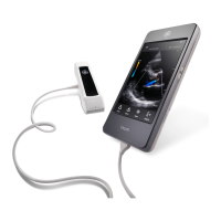
Follow these steps to remove the connection box:
1. Disconnect device from mains!
2. Unscrew 3 Phillips screws on the left and on
the right (the illustration shows the device with
the casing removed).
3. Support connection box from below, then take
it off.
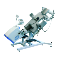
4. Disconnect the following cables, if required:
a1.Modular cable connection (B10—5) to ON/
OFF switch
a2.Miscellaneous cable connections on the
interface board.
5. Take off the connection box from below.
B-4.1.2 eBike EL: Remove Casing
Remove the casing, before repairing the drive unit and/or the power supply unit and before installing the
blood pressure module. Follow these steps:
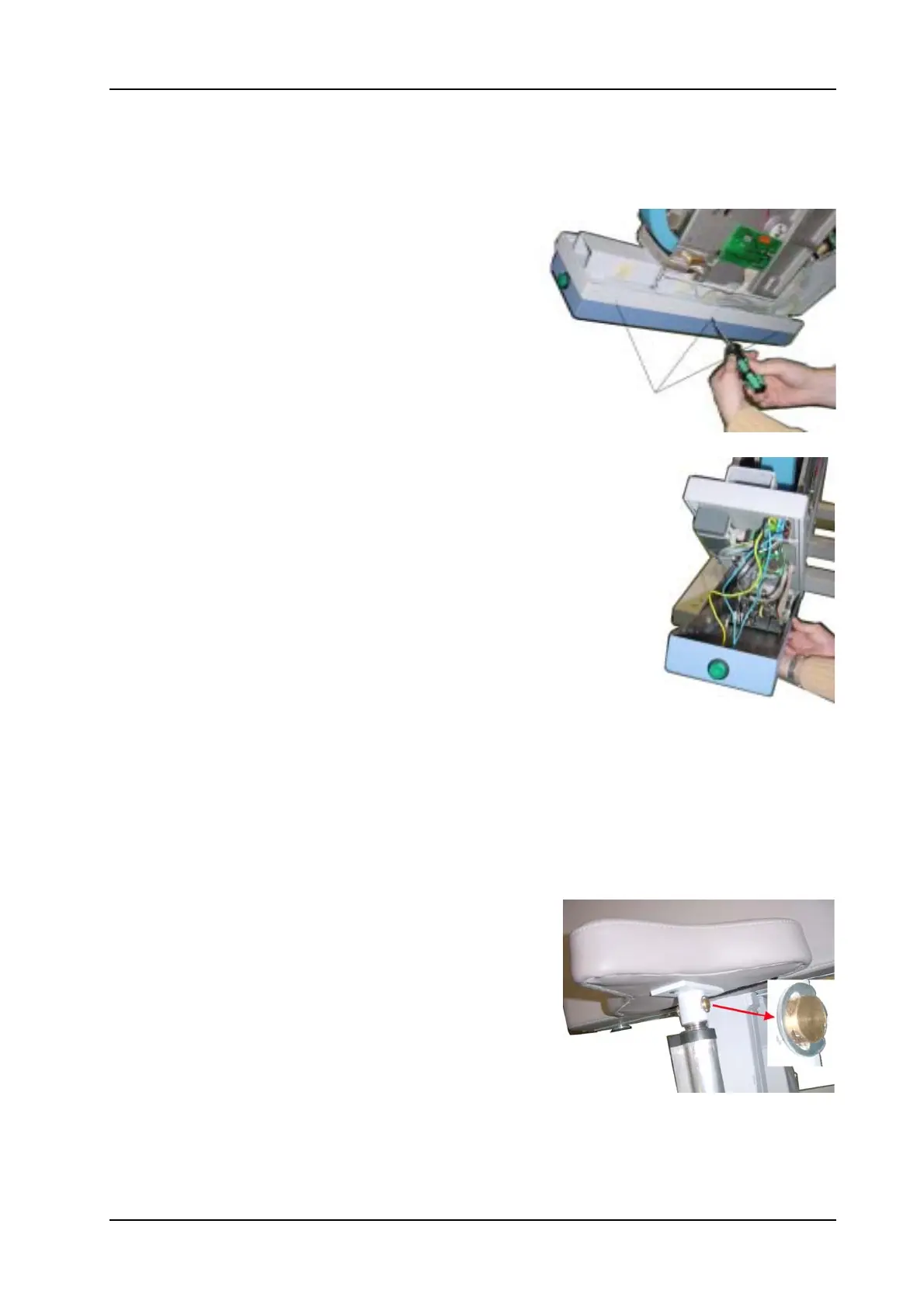
1. Remove Saddle
a. Move the saddle to a higher position and push the
bellows at the saddle support column down.
b. Remove snap ring and take out the bolt (see
illustration).
c. Remove saddle
2. Disconnect system from mains!
3. Remove connection box (see section 3.1.1)
 Loading...