Chapter 2: Installation and wiring
EST iO64 and iO500 Technical Reference Manual 65
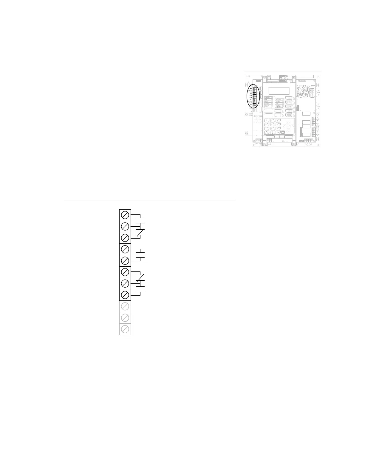
Alarm, trouble, and supervisory relay wiring (TB3)
The control panel provides alarm, trouble, and supervisory relays.
• The trouble relay changes over on any trouble event (common
trouble)
• The supervisory relay changes over on any supervisory event
(common supervisory)
• The alarm relay changes over on any alarm event (common
alarm)
Note: Relay circuits can only be connected to power-limited
sources. Relays are not supervised.
Relay specifications
• Alarm and trouble: Form C, 24 VDC at 1 A resistive
• Supervisory: Form A, 24 VDC at 1 A resistive
Relay wiring
TB3
Common trouble
relay
Common supervisory
relay
Common alarm
relay
N
NC
NC
N
N
Auxiliary/Smoke
power output
Note: Diagram is shown with the panel in a normal state.
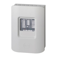
Terminal wiring location
 Loading...