Chapter 2: Installation and wiring
68 EST iO64 and iO500 Technical Reference Manual
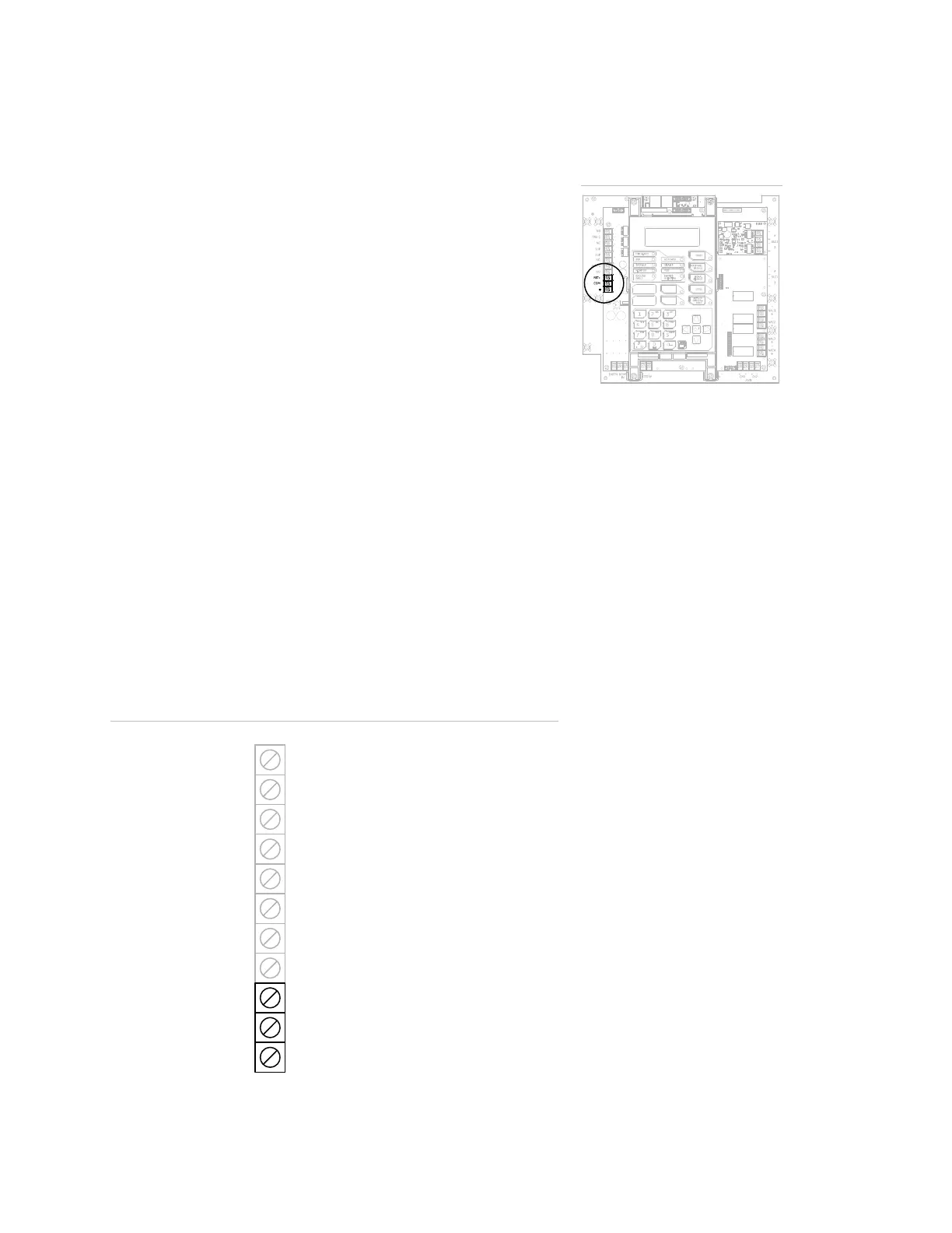
Auxiliary/smoke power output wiring (TB3)
The control panel provides an auxiliary or smoke power output,
which can be used for powering ancillary equipment or two-wire
smoke detectors. The circuit is supervised for shorts and grounds.
Note: For a complete list of devices that can be connected to this
circuit, refer to the iO64 and iO500 Series Compatibility List (P/N
3101064).
Circuit specifications
• Circuit voltage range: 21.9 to 28.3 V
• Resettable circuit (Aux power 2): 24 VDC nominal at 500 mA (1 A
possible if you reduce total available NAC power by 500 mA).
Note: If more than 1.5 A is required, you must use a power-
limited and regulated 24 VDC auxiliary/booster power supply
that is UL/ULC listed for fire protective signaling systems.
• Continuous circuit (Aux power 1): 24 VDC nominal at 500 mA.
Use this circuit for powering two-wire smoke detectors. A SMK
module is required when using the SIGA-UM module to support
two-wire smoke detectors.
Note: If more than 1.5 A is required, you must use a power-
limited and regulated 24 VDC auxiliary/booster power supply
that is UL/ULC listed for fire protective signaling systems.
• Special application circuits
• Ground fault impedance: 0 to 5 k
Auxiliary/smoke power output wiring
–
+ Continuou
Auxiliary/Smoke
power output
TB3
+ Resettable
Common trouble
relay
Common supervisory
relay
Common alarm
relay
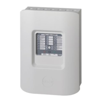
Terminal wiring location
 Loading...