Do you have a question about the GE LOGIQ S6 and is the answer not in the manual?
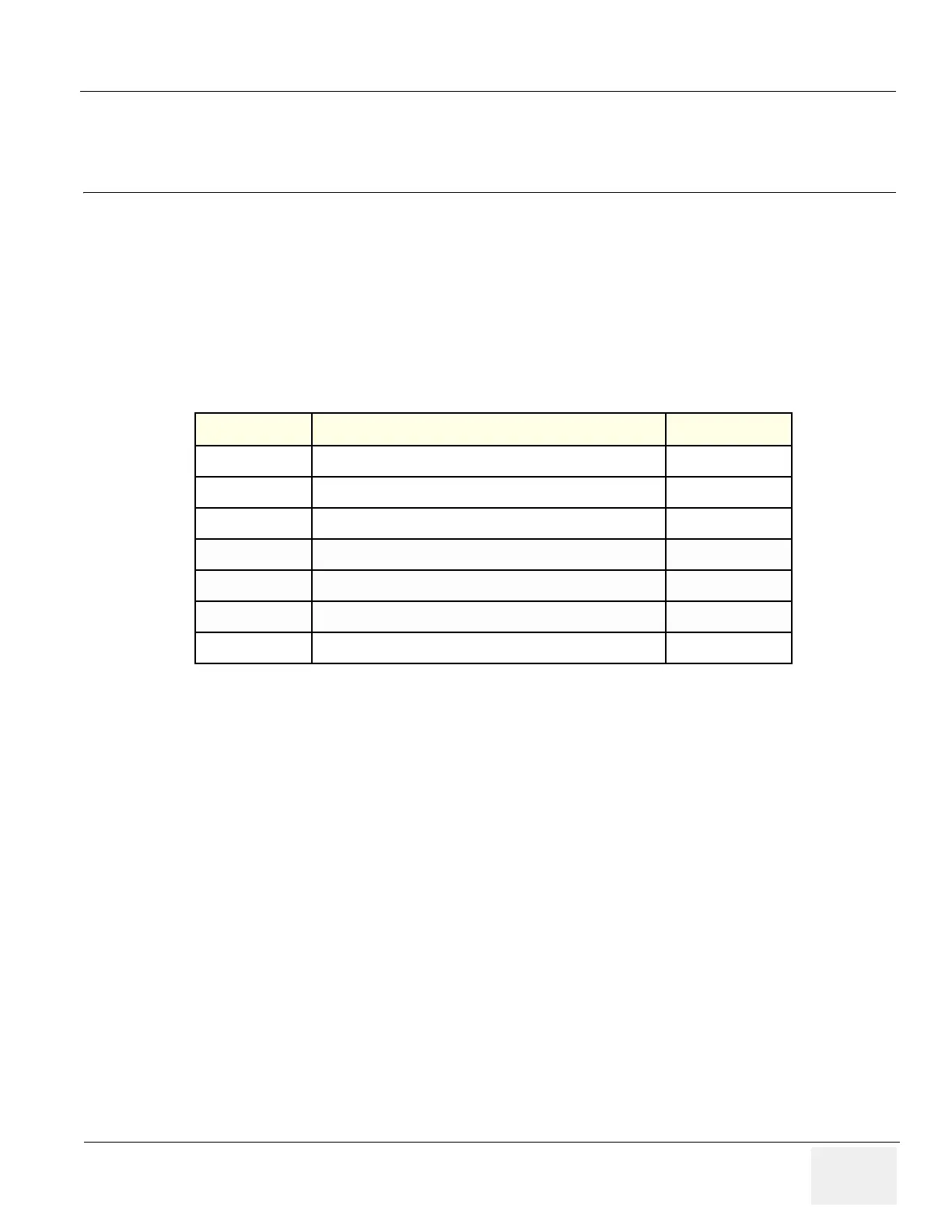
| Type | Ultrasound System |
|---|---|
| Display | 15-inch LCD |
| Power Supply | 100-240 VAC, 50/60 Hz |
| Connectivity | DICOM, USB, Ethernet |
| Frequency Range | 2 to 15 MHz |
| Imaging Modes | B-mode, M-mode, Color Doppler, Power Doppler |
| Applications | Obstetrics, Gynecology, Cardiology, Abdominal, Vascular |
| Probes | Linear, Convex, Phased Array |
| Portability | Mobile |
Manual is available in English only; customer is responsible for translation.
Lists the pages affected by revision changes.
Introduces the chapter, its purpose, and manual structure.
Details conventions for icons, safety messages, and symbols used in the manual.
Outlines critical safety precautions for operation, service, and repair.
Explains Electromagnetic Compatibility, Interference, and Electrostatic Discharge prevention.
Provides contact information for service and support centers.
Provides information for planning and preparing unit installation.
Details environmental, electrical, and EMI requirements for the console.
Outlines purchaser responsibilities and requirements for the installation site.
Specifies requirements for DICOM network function and configuration.
Details information needed to install the unit, including unpacking and testing.
Provides procedures for checking and unpacking new system components.
Lists crucial safety reminders for handling and operating the unit.
Instructions and cautions for safely moving the ultrasound machine.
Steps to verify customer order, perform physical inspection, and ensure EMI protection.
Procedures for connecting probes, peripherals, and verifying system setup.
Details required documentation and connector panel information for installation.
Introduces procedures for checking major console functions and diagnostics.
Covers lock-out/tag-out, power on/boot up, system restart/shutdown, and drive usage.
Details checks for system modes, measurements, ECG, probes, and peripherals.
A checklist for software configuration before returning the scanner to the customer.
Explains access to service software and utility menus for diagnostics.
Information on power supply test procedures and adjustments.
Log for recording service activities, problems, and comments.
Explains system concepts, component arrangement, and subsystem function.
Details compatibility of FRU parts across different software versions.
Provides block diagrams and theoretical explanations of system components.
Lists supported peripherals, particularly printers.
Describes the service platform software modules and iLinq features.
Information on operator, service, and maintenance access passwords.
Details air flow paths and filter locations for system cooling.
Provides specifications for CRT and LCD monitor input and output signals.
Describes how to test and adjust the scanner's optional features.
Instructions for adjusting the front caster brake and swivel lock mechanisms.
Procedure for troubleshooting image sensitivity issues by reloading probe data.
Guides for adjusting CRT and LCD monitor contrast, brightness, color, and gamma.
Procedure for adjusting the LCD touch panel for proper geometry and calibration.
Instructions for cleaning the trackball assembly to ensure proper operation.
Explains how to read and interpret dip switch settings on boards.
Procedure to adjust system time for new DST start and end dates.
Introduces setup and running of tools for maintaining image quality and system operation.
Provides a framework for overall diagnostic testability and fault isolation.
Describes replacement procedures for modules and subsystems.
Outlines policies for returning equipment, including decontamination requirements.
Precautions to take before touching integrated circuits to prevent ESD damage.
Guide to selecting the correct section for software loading based on system configuration.
Instructions for LOGIQ S6 R7.7.x Application Software installation with BEP4.
Provides an overview of renewal parts for the LOGIQ™ S6.
Lists common abbreviations used in the renewal parts section.
Lists parts and equipment models covered for BT08 with BECOMP4.
Lists parts and equipment models covered for BT08, LCD with BECOMP3.
Lists renewal parts for the original LOGIQ S6 (BT06) across various assemblies.
Describes Periodic Maintenance (PM) procedures for the scanner and peripherals.
Explains the importance of PM for maintaining scanner quality and gaining accreditation.
Specifies the frequency and items for PM servicing of the LOGIQ™ S6.
Lists the standard GE tool kit and specific tools required for periodic maintenance.
Details preliminary checks and system tests for periodic maintenance.
Refers to Chapter 4 for detailed functional checks of system modes and peripherals.
Outlines checks for approved peripherals and system options.
Instructions for inspecting mains cable connections for safety.
General procedures for cleaning the console, probe holders, and monitor.
Instructions for cleaning or replacing air filters based on environmental conditions.
Procedures for inspecting labeling, controls, wheels, cables, and shielding.
Guides to access diagnostic software, view logs, and run desired tests.
Covers probe care, cleaning, and visual checks for wear or damage.
Details electrical safety tests including leakage current and grounding continuity.
Troubleshooting guide for chassis, probe, peripheral, and ECG fails related to leakage current.


