5-24 MAC™ 5000 resting ECG analysis system Revision B
2024917-010
Troubleshooting: Input and Output Connectors
Input and Output Connectors
The following pages detail the input/output signals for those connectors.
The pin-by-pin descriptions identify the signal names and pin outs for
each connector on the unit.
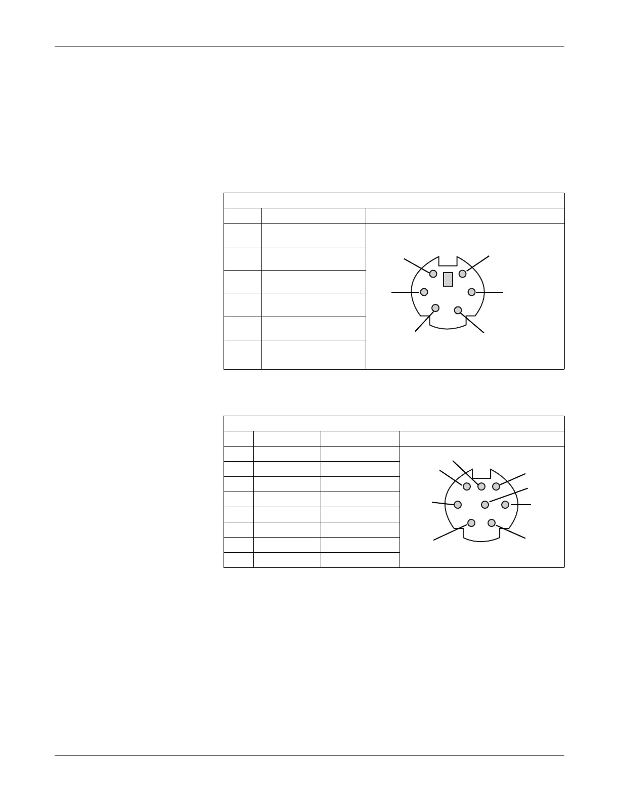
A Pins (J1)
COM1 (COM3/4) Pins (J3)
Table 2. A Pins (J1)
Pin Name
1Data
2NC
3 Ground
4+5V
5Clock
6
NC
Table 3. COM1 (COM3/4) Pins (J3)
Pin COM1 Signal COM3/4 Signal
1RTS COM3 TxD
2 CTS COM3 RxD
3TxD
4 Ground
5RxD
6DTR COM4 TxD
7 +12V
8 DSR COM4 RxD
2
1
6
5
3
4
66A
6
3
1
8
5
4
2
7
67A
 Loading...