Revision B MAC™ 5000 resting ECG analysis system 2-15
2024917-010
Equipment Overview: Theory of Operation
The following descriptions give an overview of the FPGA’s functionality.
For detailed information on the internal circuitry, refer to the schematic.
For a programmer’s eye view of the FPGA, see the source file
“hardware.h”. Where appropriate, circuitry external to the FPGA is
also described.
Board ID Register
It is necessary to identify versions/revisions of the CPU board
automatically in the field. The ATMEL primary boot code read the boot
ID port pins to identify the FPGA image and startup code required for
the board. The board ID register contains a hardwired three bit code
that tracks the FPGA image number, indicating to the ATMEL just
which FPGA image has been loaded. Three additional FPGA inputs are
reflected in this register to allow further refinement of the board
identity. Resistors (R98 and R99 through R129) are used to program the
board ID.
XBus Controller
To reduce loading on the high speed processor address and data busses,
a slow speed byte bus is provided for peripheral interface. The Super I/O
controller and SmartMedia card are both located on this bus. Unlike the
3.3V only main data/address busses, XBus is compatible with both 5V
and 3.3V logic. To maintain software compatibility with previous board
versions, the low order address byte is not used by XBus. Starting XBus
addressing with A8 also produces Super I/O addresses that easily map to
their standard PC equivalents (simply append 0x00 to a datasheet Super
I/O address offset to get a MAC 5000 Super I/O address offset).
Video Interface
LCD Controller with SDRAM Frame Buffer
Continuing problems with LCD controller part obsolescence have made
implementation of a controller design in the FPGA attractive. The MAC
5000 GUI software does not depend on sophisticated video functionality,
so an FPGA implementation of a suitable display controller can be
reasonably compact. By implementing the controller in the FPGA (using
the VHDL hardware description language) obsolescence is avoided, and
future upgrades are easily implemented.
The LCD controller is comprised of these functional blocks:
Video Timing Generator (See “Video Timing” on page 2-16)
SDRAM Frame Buffer Controller (See “SDRAM Frame Buffer
Controller” on page 2-16)
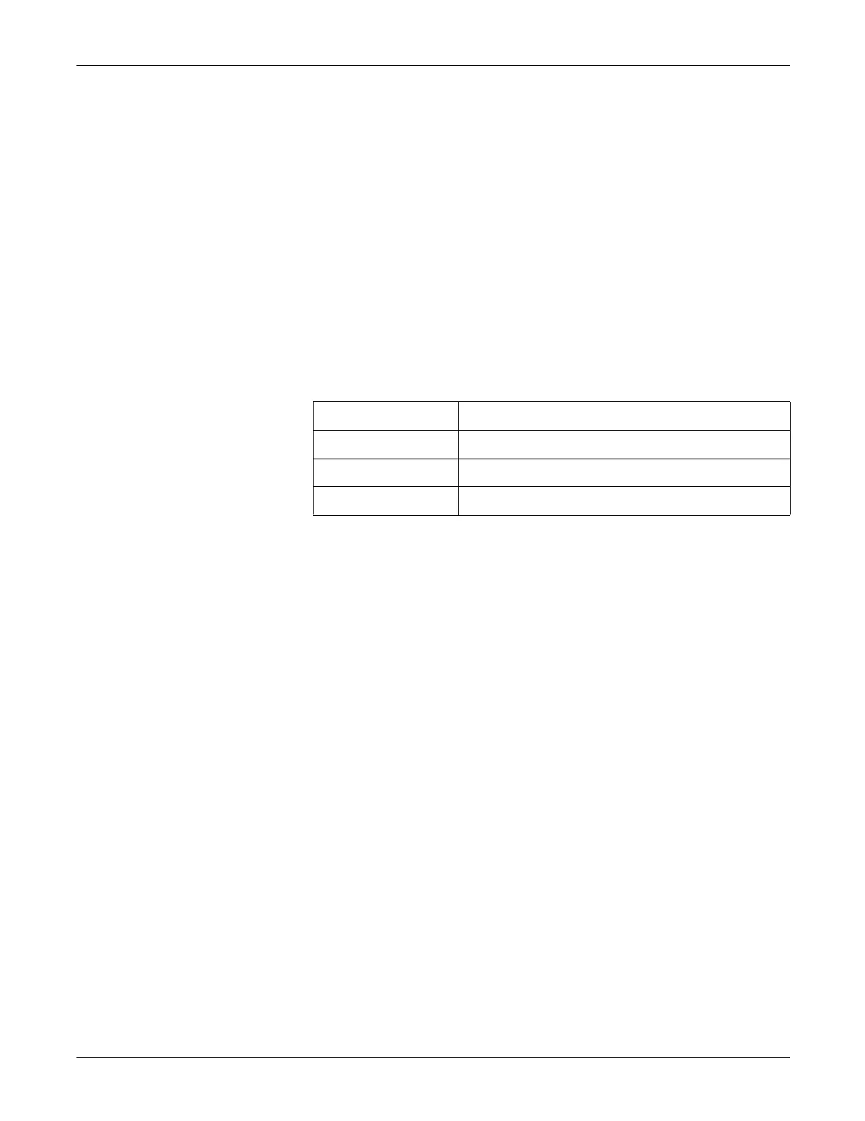
Board ID Code Versions of the 801212 CPU Board assembly
000h -001, -002, and -003
001h -004 (not used) and -005
002h -006 (this board)
 Loading...